Tech Talk
Leveraging The Latest Visualization Technology
By Erik Lundin, Sr. Mechanical Engineer

As a Mechanical Engineer, a lot of my work over the years has involved a strict form-from-function approach. The structural supports that hold bearings inside a gear box only need to hold bearings where they need to be, and withstand the forces imparted on them by those bearings. They take part of their shape from that, and part from the constraints of how they are to be manufactured. While I do find a certain beauty in a part that is entirely designed for its purpose, there is rarely any discussion about aesthetics during the development process.
But unless you are a very specific kind of person, you don’t have gear box bearing housings on display in your living room. Speakers, on the other hand, are often in or near a focal point in our homes, and we want them to look the part. This means trying to marry the visions of an Industrial Designer with the demands of engineering and manufacturing. This process usually ends on my desk. But long before that, it starts with a document detailing what kind of speaker we want. What it should do, where it should fit, and how it should work. An Industrial Designer will then make concepts that set the tone of the product. Traditionally, this discussion would often be supported by a lot of hand drawn renderings of the products. There would be studies of sizes, proportions, lines and color. This does still happen, but using computer software to create 3D sketches and renderings has taken the place of most of that. The ability to quickly drop the concept speaker in a variety of locations, sitting next to furniture or people, and rapidly changing its color and materials, takes a lot of guesswork (and pencil mileage) out of the equation.
Once we have a design we all like, I start the process of reconciling the shapes we’ve dreamed up with the realities of wall thicknesses, molding draft angles, and material properties. During this phase, there needs to be constant dialogue about changes, to make sure we are all on board with how changes to the design will impact the look of the final product. This is done by integrating modern rendering software with our CAD systems.
Rendering in Computer Graphics
In the real world, light is emitted from a source, such as a lamp, or the sun, and travels outward. It passes through some things, like gases or transparent materials, and bounces off other things, like a wood plank, before hitting your eye. There, the light is translated into information your brain interprets as the world around you, and you see the plank. Some materials reflect a lot of light very uniformly, such as a mirror. Some reflect a lot of light diffusely, such as a white cotton ball. Other materials, like a matte black paint, reflect very little light at all.
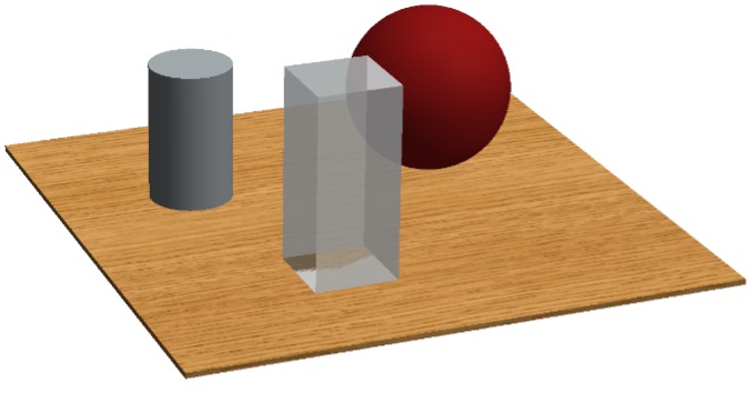
Simulating this with a computer has been known to be possible for some time. The first widely used method, scanline rendering, was introduced in the late 1960s. It used an algorithm to determine, line by line, whether or not a simulated object in 3D space would be visible to the observer. In the 1970s, this could be combined with shading models such as the Phong Reflection Model, to determine not only which objects were visible, but the shapes of their surfaces. Fig.1 has a good example of a combination of these techniques, which produces a simple result very quickly, but is not a particularly accurate representation of reality.
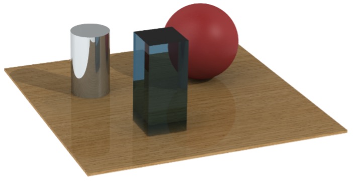
The most popular method today is called path tracing. The equations that govern path tracing were introduced by James Kajiya in 1986, and basically involve doing reality backwards. A simulated ray heads off from the “eye” in a random direction. It is assumed this ray has a value of 0, or black, until it hits something. Let’s say it hits a matte red surface. It will pick up the red color of the surface, and head off in a random direction again, and so on. If it finally hits a light source, it will pick up the brightness value of that light, and we’ve arrived at a bright red pixel to display. This is repeated for every pixel on the screen, until we have a picture. This allows realistic representations of light reflecting off surfaces and refracting as it passes through materials. Note in Fig.2 how light is distorted when passing through a glass block, and how the polished wood surface reflects light differently from the chrome cylinder.
The State of the Art
While basic path tracing was a big leap forward in making computer graphics look more realistic, there was still a lot of work to do in calculating precisely what is supposed to happen when light bounces off of various surfaces. For materials like metal and plastics, a simple calculation of how diffuse the surface is can be sufficient. But for many organic and complex materials, light doesn’t just either bounce or not bounce. Light might penetrate through the outer layers of a material and bounce off lower layers, such as with skin. Some of this light might scatter through the material and illuminate it from the inside.
Processes like this, known as subsurface scattering, haven’t been easy to model until very recently, and is one of the reasons CGI human faces look so much more realistic these days than just 10 years ago. Subsurface scattering is also used to improve the look of materials like wood, fabric, foam, and paints, materials which are widely used in speakers.
Another area which has made great advancements is that of using something called a bump map, and later a normal map, to very accurately determine how a surface behaves when light bounces off it or passes through it. In our first examples, we talked about calculating how diffuse a surface was. But surfaces often aren’t just either diffuse or not. Wood, for example, has a grain structure, and if we want photorealism we need to account for that with color, luminosity, and reflection characteristics.
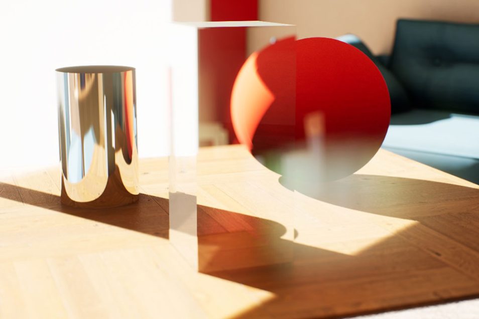
Fig.3 shows a modern path traced image with a full environment, advanced material simulation, and realistic light sources. Note how the shadow of the cylinder is lit up with red light that has bounced off the sphere, and how glare is being produced in a simulated lens. The wood is no longer a simple block, but has real depth, including surface wear and scratches.
Applications in Product Development
As is probably evident from the description of how path tracing functions, it is a very intensive process in terms of processing time and power. Over the past decade, rapid and explosive development in graphics card processors have allowed the render time of many scenes to go from hours or minutes to seconds. With some pre-computing and intelligent selection of what to show, and when, this time has even been brought into the millisecond range, putting it into the realm of real time rendering.
This has had huge implications for things like motion picture production, as green screen technology can be replaced by LED displays which react to camera movements in real time. But it also means we can interact with products that don’t exist yet during the development cycle.
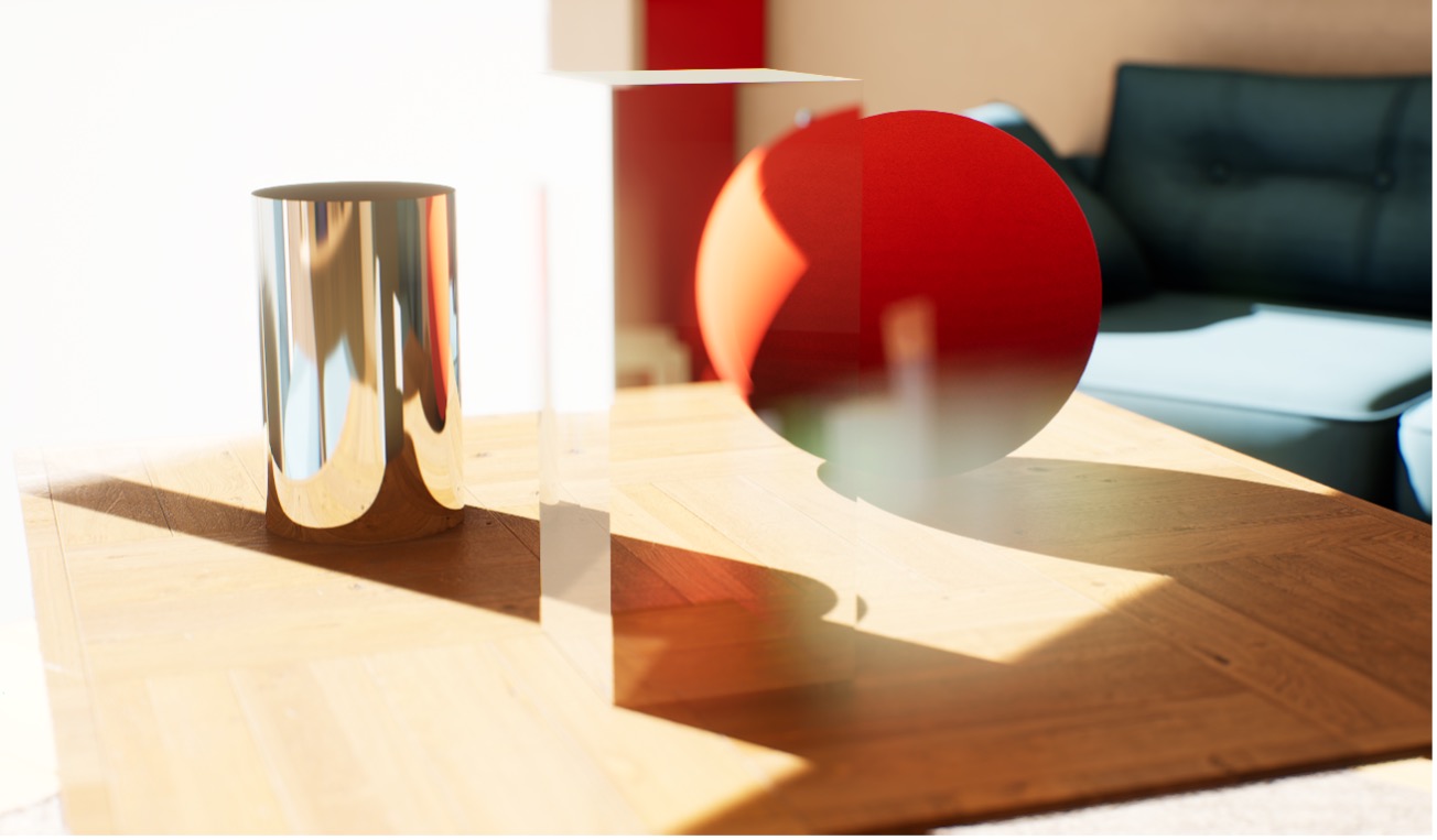
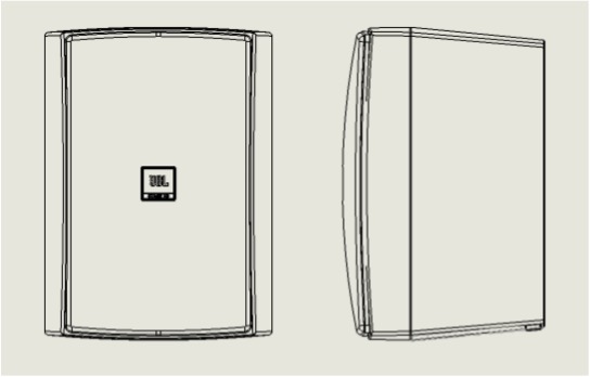
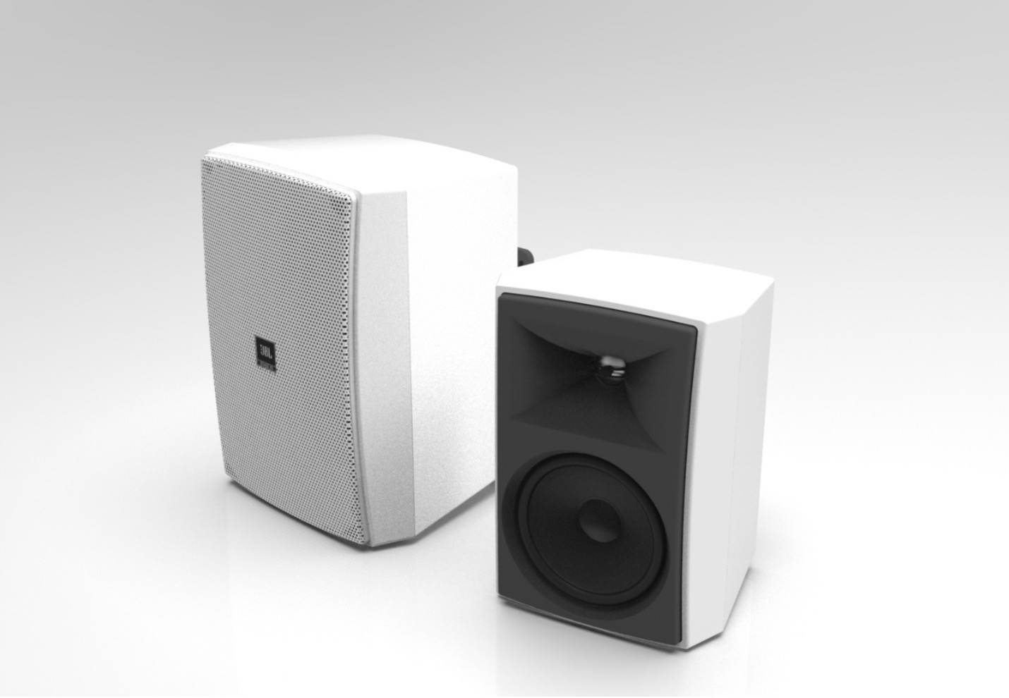
It can be very challenging to determine how certain shapes, sizes, and colors will feel in a space using just drawings. But once you see them in a room, our brains can fill in a lot of gaps using references to known objects. Let’s compare three different depictions of the same speaker, using a traditional drawing, a simple 3D render, and a render of that speaker in a familiar environment. Pay attention to how your perception of the speaker may change as you view them.
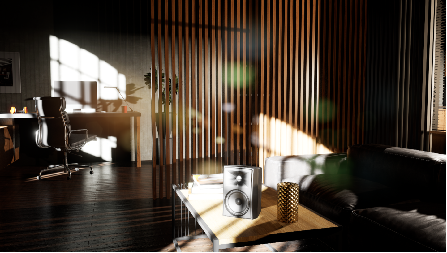
In the final image, context for the size and shape of the speaker is given by both the background and common objects around it. We have an intrinsic sense of how big objects are that we regularly interact with, and this informs our judgement of the speaker. Physical prototyping is still a vital part of any product, and so far nothing can take the place of putting the speaker on a table and looking at it. Embracing this rapidly developing field lets us stay ahead of the curve during the design process, though, and it avoids a lot of time and resources spent on physical prototypes by narrowing the field earlier on.