
Tech Talk
The Mark Levinson Approach to Class A – Class AB Amplifiers Part 2 | Distortion Reduction in Audio Amplifiers and the Role of Feedback


Introduction
The purpose of an audio power amplifier is deceptively simple: to increase the level of an audio signal without altering its character. In practice, this task is complicated by the fact that every active device introduces some degree of nonlinearity. These nonlinearities manifest as distortion—unwanted components added to the original signal that can reduce clarity, introduce harshness, or cause listener fatigue. One of the most powerful tools available to designers for reducing distortion is negative feedback, but its effectiveness and consequences depend strongly on how it is applied.
The Role of Feedback and Loop Gain
An audio amplifier employing feedback can be viewed as consisting of two main parts. The first is the forward path, which provides the actual amplification of the signal. The second is the feedback network, which returns a small fraction of the output signal back to the input. By comparing the input signal with this returned output, the amplifier continuously corrects its own errors. This self-correcting mechanism is what allows feedback to reduce distortion, noise, and sensitivity to component variations.
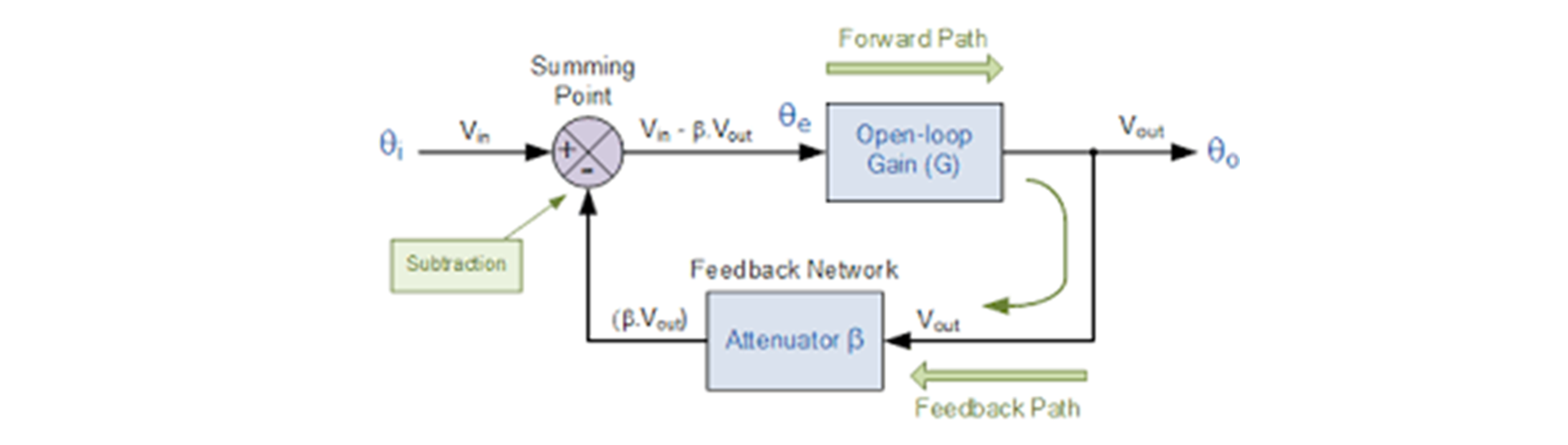
A central concept in understanding feedback is loop gain. Loop gain is the product of the open-loop gain of the forward path and the fraction of the output that is fed back. The higher the loop gain, the more strongly the amplifier can suppress errors generated within the forward path. In simple terms, feedback does not prevent distortion from being created; instead, it reduces the effect of that distortion at the output by a factor related to the loop gain. If the loop gain is large, distortion is reduced substantially. If it is small, the corrective effect is limited.
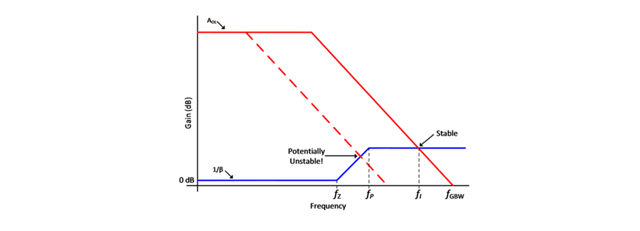
There are two fundamental ways to reduce distortion in a feedback amplifier. One approach is to increase the loop gain, either by raising the open-loop gain or by extending it over a wider frequency range. This can be very effective at reducing measured distortion, particularly at low and mid frequencies. However, increasing loop gain comes at a cost. As frequency rises, the phase shifts introduced by active devices, compensation networks, and the load itself reduce the available phase margin. If loop gain remains high under these conditions, the amplifier may become unstable.
The second approach is to reduce distortion in the forward path before feedback is applied. This involves designing the core amplifier to be as linear as possible through careful device choice, biasing, topology, and operating conditions. When the forward path is intrinsically linear, the feedback system has much less work to do. The resulting amplifier can achieve low distortion with lower loop gain, improved stability margins, and reduced dependence on aggressive compensation techniques.
Amplifier Stability
Stability is not an abstract concern in audio amplifiers. A power amplifier must remain stable with any loudspeaker and any reasonable loudspeaker cable that a customer may connect. Loudspeakers are not simple resistive loads; they present complex, frequency-dependent impedances with both capacitive and inductive components. Speaker cables add their own inductance and capacitance, further altering the load seen by the amplifier. If an amplifier loses stability under these conditions, it may enter parasitic oscillation, often at ultrasonic frequencies. Even if inaudible, such oscillations can overheat output devices, interfere with audio signals, and in extreme cases destroy high-frequency drivers such as tweeters.
Instability does not always appear as dramatic oscillation. In marginal cases, local or high-frequency instability can manifest as audible roughness, grain, or gross distortion, particularly during dynamic passages. To guard against this, designers often include various load-stabilizing networks at the output stage. While effective in preventing oscillation, these networks interact with the loudspeaker and can subtly alter frequency response, output impedance, or transient behavior. In highly revealing systems, these effects may become audible.
This is why many experienced designers place great emphasis on achieving a highly linear forward path before applying feedback. When the intrinsic distortion of the amplifier core is low, feedback can be used more gently and predictably. The amplifier remains stable across a wide range of real-world loads, requires less corrective compensation, and tends to behave more consistently with different loudspeakers and cables. In such designs, feedback serves to refine performance rather than to mask fundamental shortcomings.
From a listener’s perspective, amplifiers designed with a linear forward path and moderate feedback often exhibit a more natural and effortless sound. Measurements remain excellent, but the amplifier is also less sensitive to load variations and operating conditions. From an engineering standpoint, this approach acknowledges an important reality: feedback is a powerful corrective tool, but it works best when correcting small errors rather than fighting large ones.
Methods to Improve Linearity
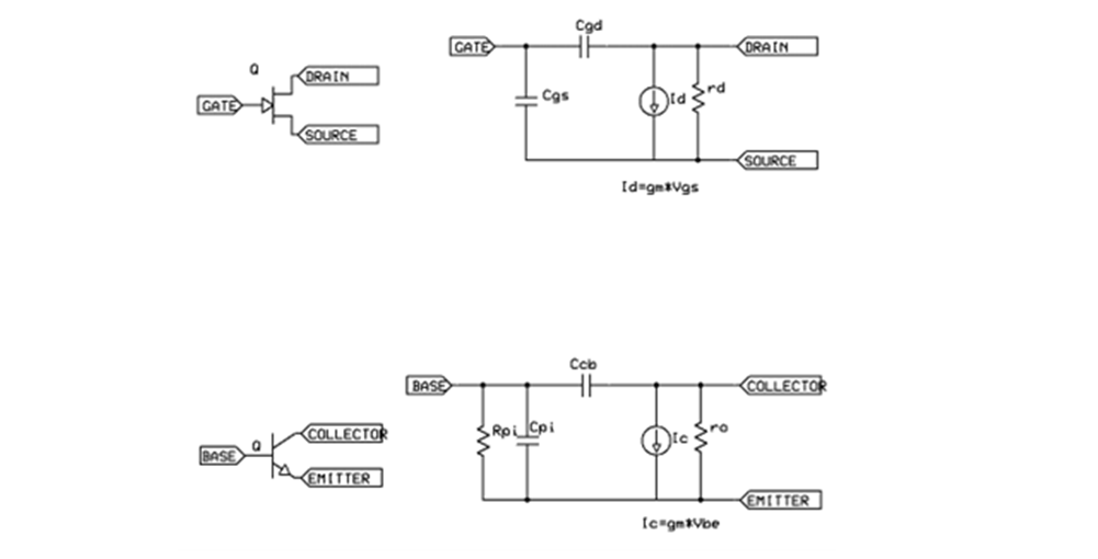
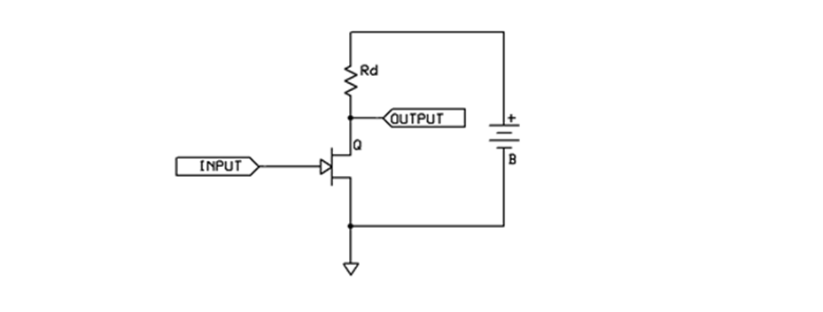
Let us now discuss a few methods of improving the linearity of the forward path. Any amplifying device—vacuum tube, bipolar junction transistor, or field-effect transistor—can be modeled as a voltage-dependent current source. The resulting π-model of the transistor is depicted in Figure 1. For simplicity, the small-signal model includes two nonlinear components: transconductance gm and output conductance ro. Figure 3 shows the π-models of the field-effect transistor and the bipolar junction transistor. To save space, we will discuss field-effect transistors, although all topologies can be implemented using other amplifying devices.
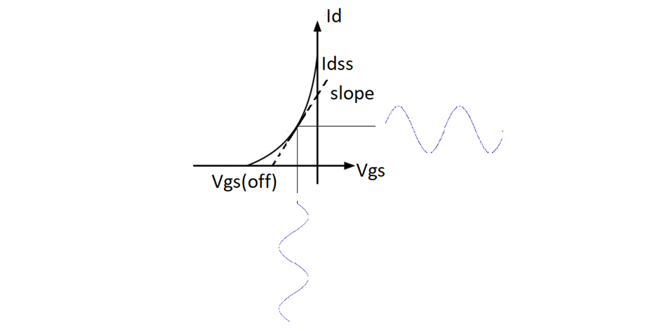
Device Output Characteristics
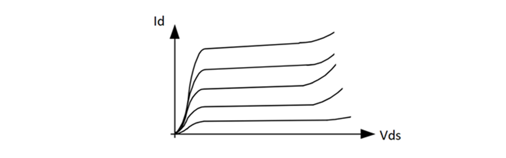
Now let us consider the output characteristics of the amplifying device. The output characteristics of a JFET describe the relationship between drain current (Id) and drain–source voltage (Vds) for a fixed gate–source voltage, as shown in Figure 9. The drain current is not perfectly constant with changes in Vds, and this dependence is nonlinear. The resulting output resistance ro appears in parallel with the load resistance Rl. Nonlinearity in ro therefore introduces distortion at the output.
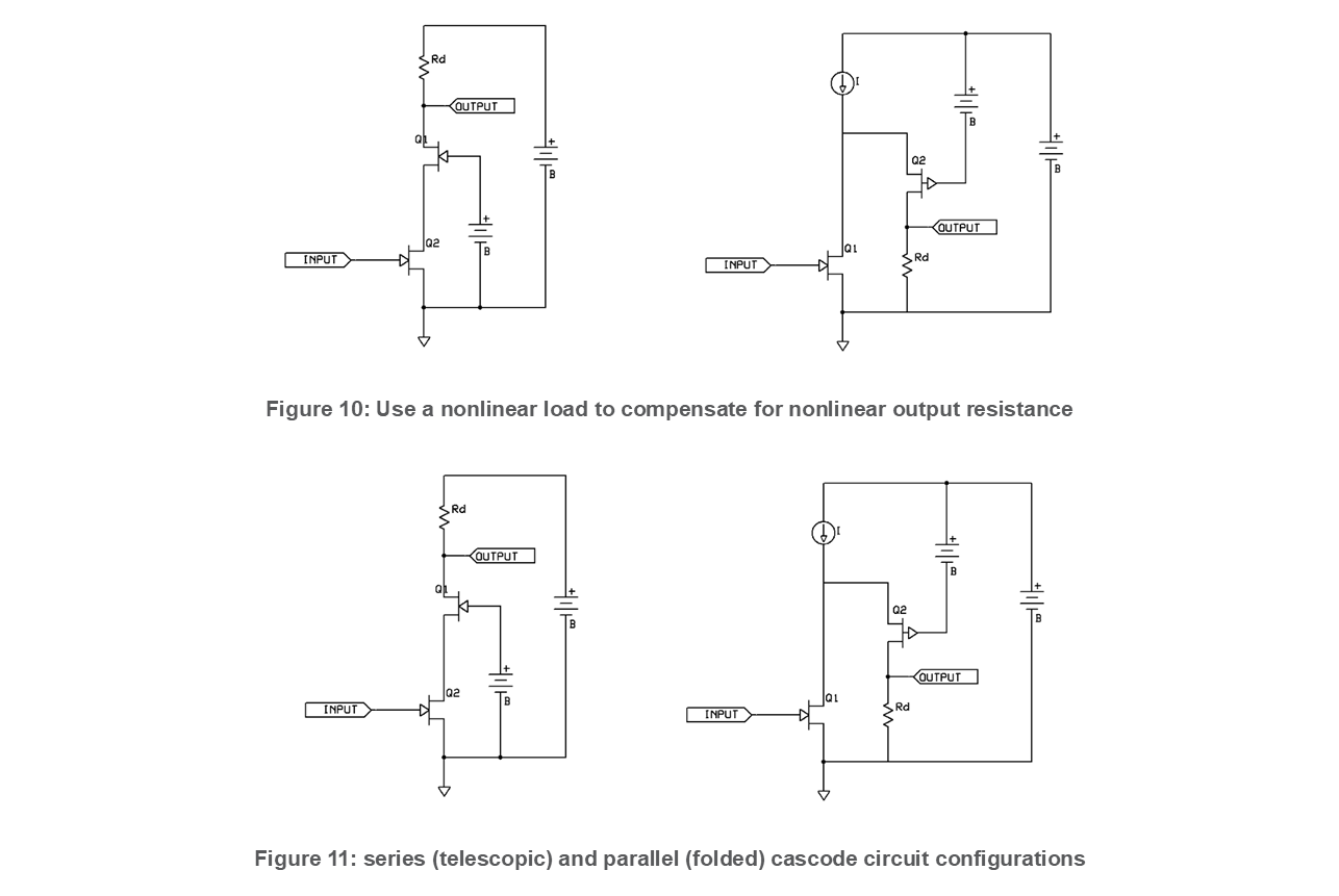
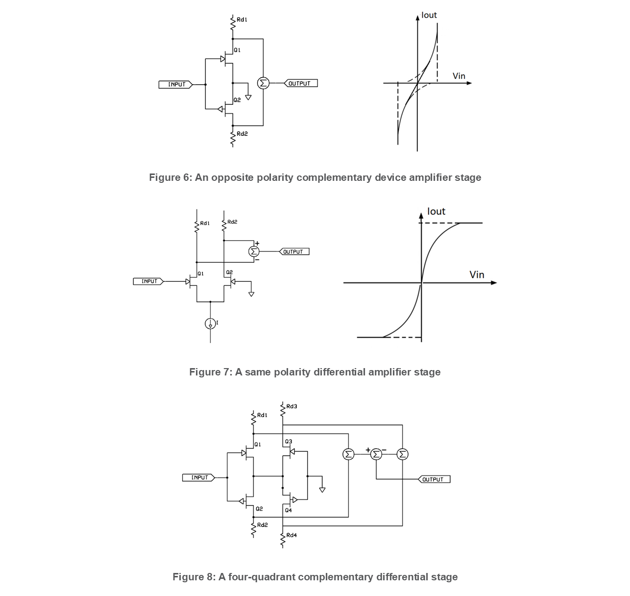
The techniques described in the later sections—such as complementary devices, differential stages, nonlinear loads, and cascodes—are all practical ways engineers reduce distortion before feedback is applied. While the details are technical, the underlying goal is simple: create an amplifier that behaves well on its own, so that feedback can fine-tune performance rather than struggle to control fundamental nonlinearities.
Feedback in an amplifier is similar to a driver correcting the steering of a car. Small corrections applied gently keep the car on course with little effort. Large, aggressive corrections may keep the car on the road, but the ride becomes unstable and uncomfortable. Designing a linear amplifier is like building a car that naturally drives straight, requiring only small steering adjustments.
Conclusion
In summary, negative feedback plays a vital role in reducing distortion in audio amplifiers by suppressing errors generated in the forward path. Distortion can be reduced either by increasing loop gain or by improving the intrinsic linearity of the forward path before feedback is applied. Because real loudspeakers present complex and unpredictable loads, stability under all conditions is essential, and excessive reliance on feedback can compromise that stability. Designing a more linear amplifier core allows feedback to operate in a benign regime, yielding low distortion, robust stability, and consistent sonic performance across real-world systems.
Detailed information can be obtained from the patents and patent applications listed below. These solutions are implemented in Mark Levinson product 5xx, 5xxx and 6xx series:
Amplifier system with output stage WO 2025/005930 A1
Bootstrapped amplifier arrangement and the application to the unity gain follower US10404222
Fully diferential amplifier US20240072746A1, EP23190335.2A
Fully differential programable gain amplifier US10720895, EP3627700A1
Plural feedback loops instrumentation folded cascode amplifier US10084421
Single-ended differential transimpedance amplifier US1150265B2, EP3979494A1
Single-ended instrumentation folded cascode amplifier and method for obtaining high common mode rejection US10601384B2, EP3453112A1