
Tech Talk
Lots of Waves in One Place
By Erik Lundin, Senior Mechanical Engineer and
Chris Hagen, Principal System Engineer

INTRODUCTION
Part of the JBL heritage is the compression driver feeding a big horn, right on the face of the baffle. Using horns as a method of getting loudspeakers to be louder first came about in the mid-1920s. One could argue that the beginning of the compression driver and horn combination came about in 1928 when using a plug in front of a radiating diaphragm to control the transition from the compression cavity to the throat of a horn was described in the Bell System Technical Journal. Obviously, that was some time ago, and the ability to accurately measure, describe, and predict the behavior of a wave has come a very long way in the past 100 years. The high-definition waveguides we use today are a far cry from the tapered tubes of yore. Which, oddly, isn’t even what we’re talking about today, but I promise it’ll all come together and make some form of sense if you keep reading.
ALL WAVES ARE WAVES
Any time a wave travels through a medium, it experiences some form of impedance. What impedance is… is a surprisingly complex topic. Electrically we say that impedance is the complex quantity of resistance and reactance, which are opposition to current flow – resistance which opposes steady state flow and reactance which opposes changing flow such as caused by changing frequency in a signal. But if you’re not an electrical engineer, I guess we could say it’s how much something tries to stop waves from waving. Now, sound waves aren’t electrical waves, but all waves behave in fundamentally similar ways. Sound waves, mechanical vibration, electromagnetic waves, all share the same features when it comes to impedance. There’s an incredible primer on this on YouTube, if you look up “Similarities of Wave Behavior” from the AT&T Archives.
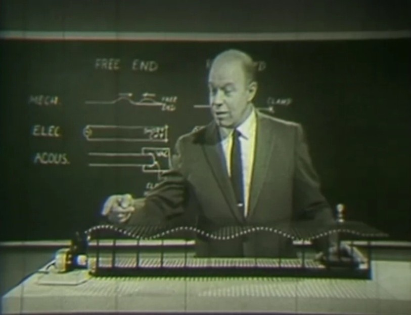
More or less, any medium we want to send waves through, including the air, presents a “characteristic impedance” to those waves. For the mechanical waves shown in the video I mentioned, this impedance is just the inertia of the moving parts, and becomes represented by the speed at which the wave moves through the medium. When we enclose sound waves in a constrained space, the shape and size of that space impact the characteristic impedance those waves experience. This means that the impedance inside the mouth of a person yelling is very different from the impedance of the air around them. A simple bullhorn, also seen in the video, presents a gradual taper to gently transform the impedance, making the yelling person… louder. And I promise this is still going somewhere. I just need another quick detour on the way.
DUAL DIAPHRAGM COMPRESSION DRIVERS
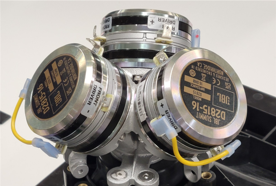
When working on the new JBL Summit series, we updated several of our dual diaphragm compression drivers. Fundamentally, the dual diaphragm compression driver is a more efficient development on the standard compression driver, with two diaphragms firing into the same compression chamber, allowing us to increase the output power of the sound without as much of an increase in load on the amplifier. There are other benefits too, in sensitivity and heat management, but with big speakers it’s fun to talk about big sound. We want to push the performance of the system, and that means the high frequency section needs to keep up with big, powerful woofers.
With the JBL Summit Series, this was, frankly, still not enough. We needed more compression drivers feeding the waveguide. The reason why will be answered in a future Tech Talk, it’s not important for this topic.
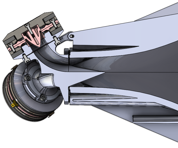
A cutaway showing the acoustic path from a single compression driver, through the manifold, into the waveguide. The path looks like it narrows for a while, but this is an optical illusion. It is expanding sideways as it changes from a round cross section into a slice-of-pie shape.
WHERE?
Well, if you’ve looked at a front facing waveguide, you know it narrows down to meet the exit of the compression driver. This is completely necessary, remember how that tapered tube was an impedance transformer for the sound waves? But with multiple compression drivers, how do we mix all their outputs without introducing more of an impedance mismatch?
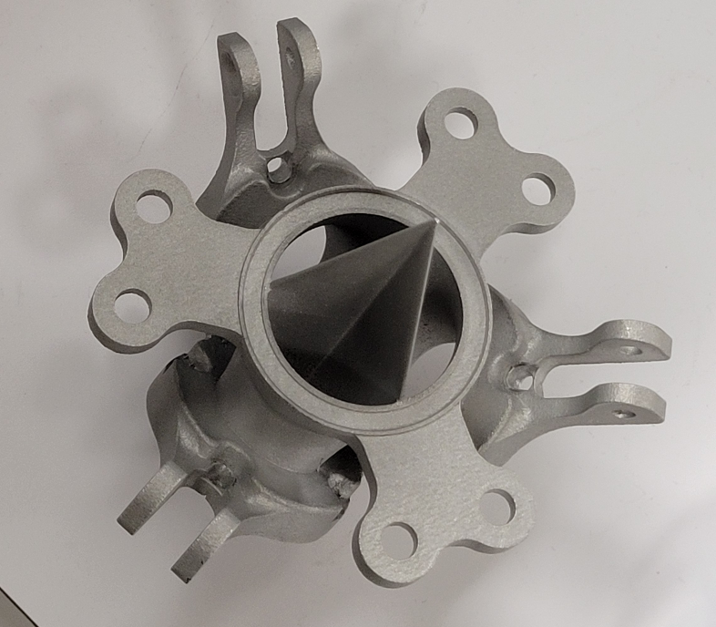
One issue to overcome is that the soundwaves “prefer” to go through either constant compression or constant expansion but do not like transitioning from compression to expansion or vice versa. We can’t allow it to start expanding, and then force it to compress again, without that mismatch. So we couldn’t just aim all the compression drivers into a box that allows them to expand and then mount a waveguide to the box forcing the sound to compress into the waveguide throat. We went through a rather long period of testing over a dozen 3D-printed prototypes, attempting to get all the waves to constructively reinforce each other. Ultimately, the solution was to feed three compression drivers into individual tubes. These tubes had a very similar expansion ratio along their length as the exit of the compression drivers themselves, acting almost like an extension of the summation chamber.
As the wave travels along the tube, the tube gradually changes shape from the round entrance to a third-of-a-pie shape at the exit. The three tubes could then be joined together and form one single, circular exit, the cross-sectional area of which is slightly larger than the sum of the three compression driver exits. This allows a continuous expansion of the wave. We did end up adding another transforming element to the interface between this tri-manifold and the waveguide, but that’s a topic for another day.
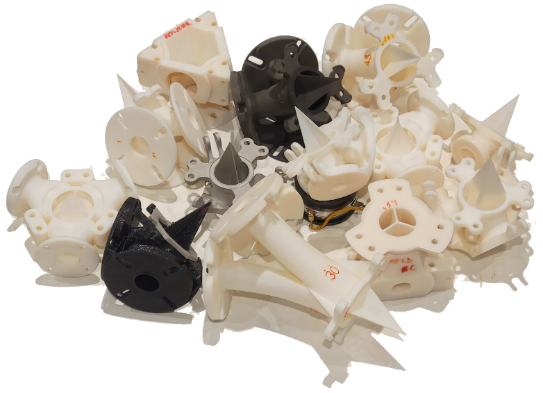
MECHANICAL CONCERNS
Well, we did spend a lot of time working on the impedance matching part of this problem, but the mechanical problem solving was no less intense. Attaching three compression drivers in close proximity to each other to a single manifold, having access to their mounting screws, and meeting the acoustical demands we outlined earlier took a lot of experimentation and time. To minimize the length of the tubes, the drivers needed to be mounted off-axis and have their tubes bend into place. Fortunately, the repelling magnet forces of the high-energy motors has not caused too many complaints from assemblers!