
Tech Talk
Elliptical Inverted Surrounds
By Erik Lundin
Senior Mechanical Engineer, HARMAN Luxury Audio

Introduction
It’s been said, by those wiser than myself, that restrictions breed innovation. Sometimes the limits are technical, sometimes they’re just in our mind, but they always give us a reason to figure out a way to get past them. In the case of some speakers we had a concept for, the industrial designer wanted a slimmer cabinet, and the acoustic engineer wanted a bigger diaphragm. They both wanted as small a gap as possible between the diaphragm and its trim ring.
Now, if you want a small gap around the cone, all you need to do is use a smaller rubber surround. Which, of course, was also not an option for the amount of excursion the acoustic engineer had in mind. So, with my limits firmly in place, the time came to start thinking outside the box put in place by the last 100 years of electrodynamic speaker drivers.
Starting Point
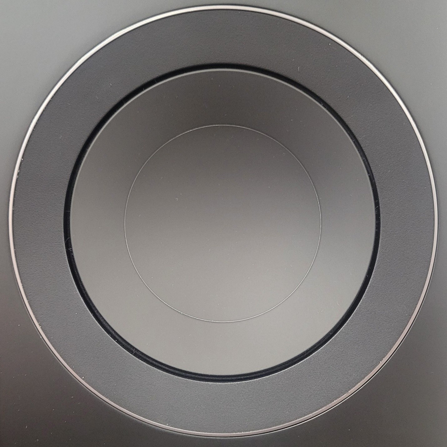
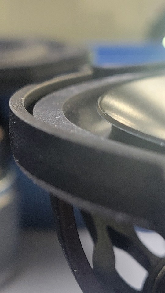
Most woofers and mid-bass drivers use a semi-circular rubber surround to hold the diaphragm to the frame. This allows the voice coil to push up and pull down on the diaphragm while the surround flexes to keep it centered, and provide resistance to it moving too far. The semi-circular design is very simple to make, and behaves very predictably in both directions. Sometimes the shape will be one of concentric ripples, but we’re going to ignore those in this talk. The semi-circular cross-section of the surround is generally facing “out” towards the room, but in cases where we want to hide it more, the roll can face into the frame, creating what is usually called an “inverted surround.” This is where we started, aiming to cover up part of the “gap” with a trim ring. However, this would have necessitated making room for the surround inside the frame, and restrictions on the cabinet size meant we just couldn’t fit it. So I started by simply making the cross-section of the surround into an ellipse of the same circumference as the regular semi-circular surround.
The Big Problem
Feeling pretty great about my solution, I headed into the world of simulations to verify how smart I was. Well, as they sometimes do, the simulations provided a great check to my ego, because there was a very big problem. I had completely neglected to take into account that 100 years of conventional wisdom were there for a reason. The semi-circular surround provides approximately as much resistance when the diaphragm is being pushed out as it does when the diaphragm is being pulled back in. The elliptical cross-section surround does not. So, I had solved two small problems by creating a big one. The speakers would look good, but sound terrible. Obviously, that’s not how we do things, so I went back to the drawing board.
Solutions
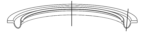
I began by trying to simulate some options where the thickness of the surround changed along its cross-sectional length. I tried adding reinforced spots to bias the resistance in one way versus the other. They worked, but it was not elegant. My final shot was angling the semi-major axis of the ellipse away from the axis of operation of the diaphragm, and suddenly the solution was right in front of me.
Fine Tuning
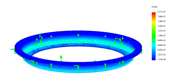
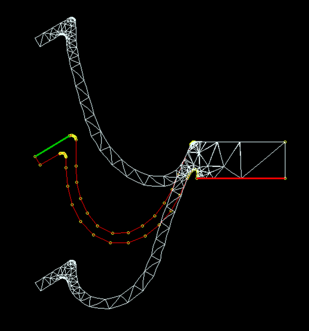
With the size in place, we had to make some tweaks to allow for ease of manufacturing. Once those were in place, we used simulation software to quickly iterate through small changes along the edges to match the forces of our new surround to a known example. The software works on a 2-dimensional slice of the surround. Because it is symmetric around its operating axis, we can extrapolate the results as valid for the entire part, at least when it comes to the things we’re measuring here. This is a much simpler form of Finite Element Analysis than full 3D, but you can read my Tech Talk about FEA if you want to know how that works. The big advantage of this simplified approach is that I could iterate through dozens of tweaks in an hour, instead of maybe one or two.
There’s always a concern, working with simulations, that the math won’t accurately match reality, and obviously once you make the tooling to create a new surround, you’re paying for it. Thankfully, we’re in the business of pushing the envelope, and it paid off. The new elliptical inverted surrounds are in all the woofers and midrange drivers of the new Revel and ARCAM lines of speakers.