


Tech Talk
How to Connect a Turntable to a Mark Levinson Preamplifier
Dimitri Danyuk
Senior Principal Engineer

A phono cartridge, also known as a turntable cartridge or pickup, is an electromechanical transducer that converts the mechanical vibrations of a record's grooves into an electrical signal. This signal can then be amplified and played through speakers. A stereo cartridge has four pins, marked with the following color code: Left channel is white, Left channel ground is blue, Right channel is red, Right channel ground is green. Each cartridge channel is connected to the corresponding RCA connector with wires, usually having the same colors. The RCA connectors are mounted in a metal box with the tonearm and other metal parts of the turntable electrically connected to the same box. The ground terminal (binding post) is mounted on a metal box for a dedicated ground lead to the chassis, tonearm and the head-shell. There is no connection between the cartridge wires and chassis ground, and the phono cartridge is a floating signal source.
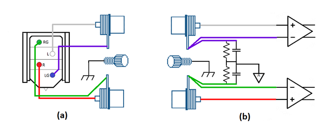
Figure 1 (a) Block diagram shows the basic turntable cartridge wiring; (b) Block diagram of the Mark Levinson input portion of the phono circuit.
Balanced operation always provides the benefit of common mode interference rejection. A phono cartridge is a floating voltage source and is suited to the advantages of balanced mode. In Mark Levinson gear, a balanced connection has been incorporated in every phono stage (5xx and 5xxx series) for years.
While a true balanced connection offers superior noise rejection, the industry continues to use RCA connectors for phono connections, and they are inherently unbalanced. The front-end portion of the Mark Levinson phono stage is shown in Figure 1(b). The balanced inputs of the front-end amplifier are connected directly to the RCA connector, while the shell of the RCA connector is tied to analog ground through the resistor (50-100Ω) and the capacitor (0.5-10nF). This circuit allows the user to utilize different cables between turntable and phono stage.
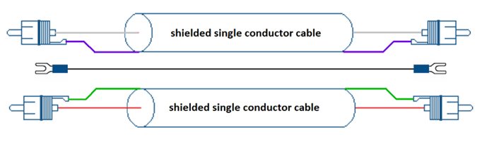
Figure 2 Single conductor shielded cable
A shielded cable is an electrical cable that has a common conductive layer around its conductors for electromagnetic shielding. This shield is usually covered by an outermost layer of the cable. The shield acts as a Faraday cage – a surface that reflects electromagnetic radiation. This reduces the interference from outside noise onto the cartridge signal. However, this cable is not symmetrical and susceptible to magnetic fields.

Figure 3 Twisted shielded pair with the shield, connected to the RCA connector shell at one end
A twisted pair reduces susceptibility from outside magnetic field to the pair and the shield improves the rejection of external electromagnetic interference. An RCA connector with connected shield can be attached either to the preamp input or to the turntable output. The best orientation can be determined by a few trials for the lowest level interference.
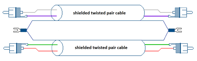
Figure 4 Twisted shielded pair with the shield, connected to the chassis ground at both ends.
This cable offers the best suppression of the unwanted interference with the cartridge signal. The only unbalanced parts are the RCA connectors themselves. In the Mark Levinson laboratory, we are using Mogami twisted pair W279 or Canare L2-E5 for the MM (moving magnet) cartridge cable and Mogami star quad W2893 or Canare L2-E5 for the MC (moving coil) cartridge.

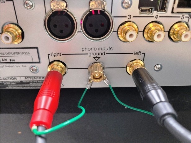
Figure 5 Photos of the twisted shielded pair cable, shown in Figure 4. The shield of both cables are connected to the chassis at both ends.
Further reading:
Sound System Interconnection, RANE application note, https://www.ranecommercial.com/legacy/pdf/ranenotes/Sound_System_Interconnection.pdf
Dave Davenport, Audio Component Grounding and Interconnection https://www.musicapristina.com/media/audio-component-grounding-and-interconnection.pdf
Van Den Hul, Audio and Video Cable/Connector Wiring Diagrams