Tech Talk
Aluminum Capacitors
Gary Crocker
Principal Engineer, Hardware | Mark Levinson

A capacitor is a passive component that stores and releases electrical energy. There are many different types and they are used throughout electronic circuits. If you look at the picture above you'll see a bank of capacitors. In this Tech Talk I’m going to concentrate on Aluminum Electrolytic Capacitors.
Construction of a Capacitor
The basic principle of the capacitor is to store electrical charge, the symbol for charge is Q and it is measured in coulombs. The potential charge a capacitor can hold is determined by the capacitance (symbol C and is measured in Farads) and the voltage applied (V measured in volts). This gives us the equation: Q = CV
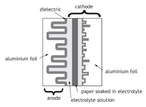
In large electrolytic capacitors the plates are commonly made from Aluminum.
There is another factor that impacts on the capacitance value, this is the material that is placed between the plates, this is called the dielectric. Before I talk anymore about dielectric, let’s talk a little about capacitor physical construction. To maximize the capacitor plate surface area in the smallest case size the Aluminum plates are made from a very thin foil, typically 0.05mm to 0.11mm. To maintain a physical gap between these thin plates and to stop the two plates shorting together a paper or tissue is used. Paper or tissue material is used to absorb the liquid dielectric.
Let’s imagine there was no material between the plates, just a perfect vacuum, obviously impossible, but stay with me and remember that capacitance is all about area (A) and distance (d). The permittivity of this free space or vacuum is a magic number of 8.85 x 10⁻¹² Farads per meter. This physical constant reflects the ability of an electrical field to pass through a vacuum and is denoted as Ɛ0, for the sake of this tech talk, let’s just accept this constant.
As we know, there must be a physical material called the dielectric between the plates of aluminum, the physical parameter of the dielectric is called the relative permittivity and is demoted as Ɛr. The capacitance value can be determined by this equation:
During the construction of the capacitor, before the plate-electrolytic-plate sandwich is rolled the anode aluminum foil which will later become the positive terminal, goes through an etching process to increase the surface area (A). The dielectric layer of aluminum oxide is formed on the anode foil electrolytically. This aluminum oxide layer is very thin, in the order of 0.045 microns, making distance (d) very small.
After winding the electrolyte solution is added to impregnate the paper between the aluminum foils.
Next the capacitor is assembled into its case.
The next step is aging and testing. The aging process will repair any damage to the oxide layer during winding and assembly process. This process may take serval hours to complete.

Use of Reservoir Capacitors in Mark Levinson Products:
Aluminum capacitors are primarily used for power supply bulk capacitance or also known as reservoir capacitors. They are used to store the DC voltage after rectification (where AC is converted to DC, usually with diodes). An example:

As can be seen from the blue waveform above, the voltage on the capacitor is charged by the peak of the rectified AC waveform. For typical mains connected products this charging and discharging occurs at double the mains frequency, depending on where you are in the world, 100-120Hz. The reservoir capacitor is doing its job and storing charge between each charging pulse. The greater the load on the power rail the more the capacitor voltage will droop between each charging pulse. This constant charging and discharging produce internal heat to be generated. The power supply designer must ensure this heat rise will not reduce the capacitor life span. The generated heat accelerates the evaporation of the liquid electrolyte. Elevated environmental temperature also has a detrimental effect on life expectancy. Other capacitor parameters change with age, the designer must also take these into consideration for expected product design life.
Mark Levinson use large value reservoir capacitors in most products. In the ML50 pictured at the beginning of this documents there are twenty reservoir capacitors for the power amp section adding up to a total of 89,000uF. This large amount of storage is required to ensure little voltage droop when the amplifier is driving heavy or difficult loads.
References:
Nichicon Corporation - General Descriptions of Aluminum Electrolytic Capacitors
Kemet BHC components – LAS34/35 Series Screw Terminal Capacitors