

Tech Talk
Simulating Mechanical Parts
By Erik Lundin, Sr. Mechanical Engineer

Introduction
There are many competing physical attributes that make up a good speaker. Volume, shape, component placement, materials, weight, rigidity, ease of production; all need to be taken into account. And when we’re done, we’d prefer it to also look amazing.
Getting all these variables right involves the entire team, and after a while some of the answers feel very intuitive. We know approximately what materials and shapes will support a certain transducer just from experience. But in order to innovate we need to also push beyond our comfort zones, and that often involves doing things in a way we haven’t before. But that doesn’t mean we need to work blind.
History
In the early days of engineering, gut feeling and experience were all that anybody had to go on when designing a physical structure. But thanks to geometry, we’ve been doing more than guessing for quite a while now. The simplest calculations of structural load can easily be used to figure out the stresses and strains on a triangle made of a known material. I know this seems miles off from how to figure out how stiff a speaker cabinet is, but bear with me, I promise this all ties together in the end.
Method of Joints
Let’s consider a triangle, supported at the bottom left and bottom right, with a weight of 10 units pushing down on it. We know that the triangle is 5 units tall and 6 units wide. Let’s divide it into two right angle triangles, with legs of 5 and 3 units, so that we can get some help from old Pythagoras! We can calculate the length of the sides as √(height2+width2), or √(25+9), which gives us approximately 5.83 units.
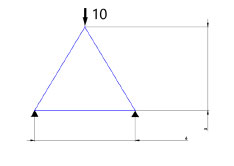
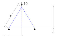
We can now conclude that the bottom left support is experiencing some amount of force along it from our 10 units of force up top. Because we know the lengths of all our legs, we can easily work out that ratio. By dividing the length of the hypotenuse by the vertical height, we get 5.83 / 5 = 1.166. We can assume that the bottom left support is holding half of the force pushing down, so 10 / 2 = 5 units. 1.166 * 5 = 5.83 units.
Now, the legs of this triangle are in one of two conditions, either compression or tension. The legs on the sides are being compressed by the load, but the leg on the bottom is being pulled apart, since the load is trying to flatten the triangle out.
This means our horizontal calculation goes the opposite way. So with the lengths in opposite positions from the previous calculation, 3 / 5.83 = 0.515. We multiply that by the load we calculated to get 0.515 * 5.83 = 3, but we’re only calculating half of it, giving 1.5 units of horizontal load per side.
So now we know how much stress each of our legs is under from the load we applied. What good does that do us? Well, not much right now, but if we imagine putting in more triangles, we could use them to construct a truss bridge, using nothing but simple pen and paper math!
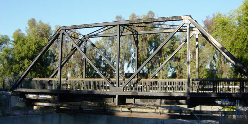
I know, that doesn’t look much like a speaker cabinet, but I promise we’re getting there.
Truss bridges, especially old ones designed with hand calculations, are generally straight, and have very uniform shapes. The loads are all known and easily calculated. But what about a vibratory load inside a bent piece of wood? That is vastly more complicated and can’t easily be described with simple equations. But what if we turned the entire speaker cabinet into a giant pile of triangles?
The Finite Element Method
Obviously, that’s quite the simplification, but the Finite Element Method is a generalized numerical method for solving partial differential equations by subdividing the large or complex system into a smaller, simpler parts. These are the titular “finite elements”.
This method of calculation was independently discovered in several places around the 1940s and 50s, in the USA, USSR, and China. Throughout the 60s, the complexity of available software increased rapidly with available computing speeds. These days, a desktop computer is capable of solving very complex systems in a matter of hours.
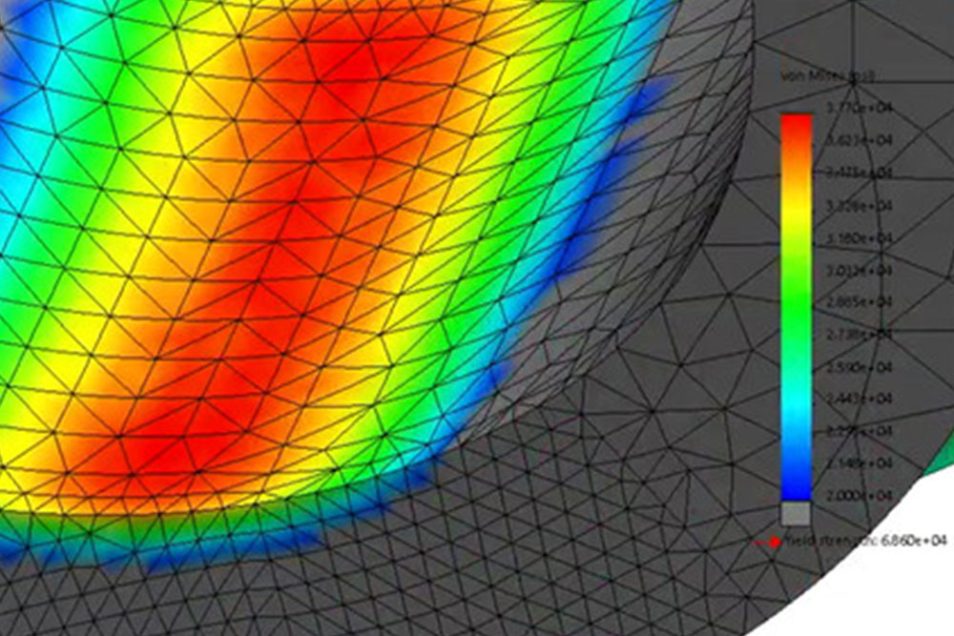
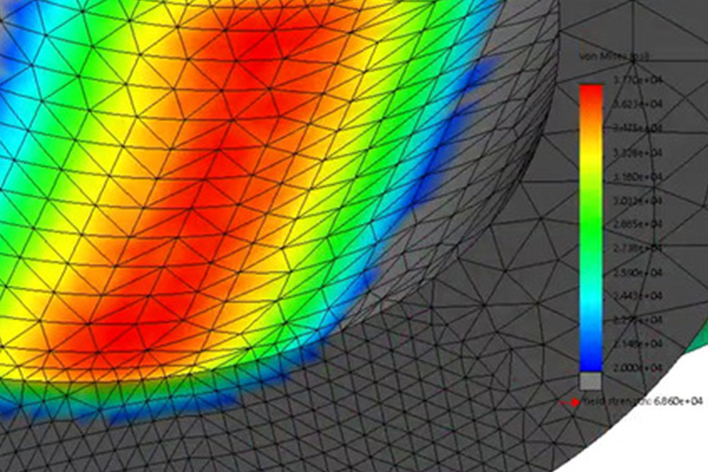
We start by creating the “mesh”, which is a big stack of those finite elements, which approximate the shape of the actual problem. This allows the problem to have a finite number of “points”, much like the points in our original triangle. Obviously, the fewer points, the faster this goes, but the less accurate the results will be. The specifics of creating the mesh are always a compromise between accuracy and calculation time.
Finite Element Analysis
The practical application of FEM is called FEA, which can be considered an analysis of the mesh we created. Now, one of the beautiful things about this is that we can analyze lots of different things using the same mesh! We can calculate loads and stresses, heat dissipation, basically anything that involves a physical property.
Obviously, we’re no longer doing math on pen and paper for each of these triangles either. The computer takes our desired loads and supports and then starts an enormous chain of math for us, and outputs the results graphically or in a table. This is now one of the many ways we validate our assumptions when designing parts for speakers. It allows us to design and build parts that are as simple and light as possible while performing optimally.