
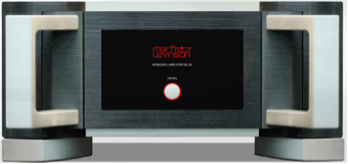
Tech Talk
Technical Highlights of the Mark Levinson ML-50 Amplifier
By Danial Shimiaei | Director of Engineering, Mark Levinson
The ML-50 amplifier was built to celebrate 50 years of industry-leading audio designs from the Mark Levinson brand. As part of its development, our engineering team was challenged to improve upon the performance of the award-winning Nº 536 amplifier in every aspect possible. To achieve this lofty goal, we focused on five key areas of the design.
Input Circuitry
One of the most impressive features of the ML-50 is its sound quality. That begins with the input circuitry. A new input board was designed with a patent pending fully differential (balanced) circuit that includes an enhanced method of increasing output voltage symmetry, reducing distortion, and improving overall stability. Within this board, an abundance of individual heatsinks are utilized on smaller transistors to ensure stable and reliable operations for years of consistent operations. With this improved and incredibly clean input circuit, we turned our focus to the output stage.
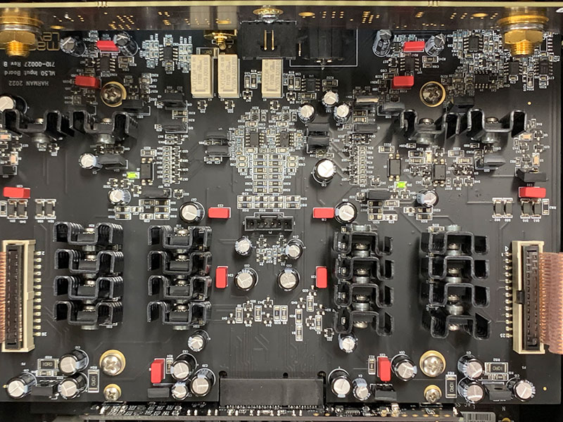
ML-50 Input Board
Output Circuit and Reserve Power
While the core output circuitry of the Nº 536 amplifier was retained, we sought to increase both overall rated power and dynamic capabilities for improved transient response. To achieve this, we increased the Class A bias to 20W RMS at 8Ω, and pushed the Class AB output to 425W RMS, with the ability to double that into 4Ω, and to be stable at 2Ω.
The power supply capacitance bank of the amplifier modules was increased significantly now holding 263,400μF in reserved storage to deliver power for the most demanding dynamic range requirements and not leave the output stage power starved. In addition, the massive custom toroidal transformer is capable of delivering immense amounts of power and allows the high-current output stage to drive even the most challenging loudspeaker loads.
ML-50 Transformer & Output Channel Capacitors
Thermal Profile
One challenge of the increased Class A bias and output power is the additional heat that is generated within the amplifier. In terms of power consumption, class-A amplifiers use a significant amount of power even when there is no audio signal present, and this directly translated to an increased thermal profile.
During the design phase, the ML-50 was estimated to require dissipation of about 500 watts of idle power. It is challenging from thermal management and mechanical design aspects to dissipate that heat without forced air cooling. A forced air cooling system can result in unwanted mechanical vibrations and acoustic noise in the listening environment, something that was unacceptable in the ML-50.
To achieve proper convection thermal management, the ML-50 chassis is fitted with strategically located venting slots on the bottom, top, and inside the chassis to complement the externally mounted heatsink fins in allowing for proper convection cooling of the electronics from the inside of the chassis.
Processor & Fault Detection
In design of high-power output amplification, it is paramount to ensure long term stability and protection during all modes of operation, as well as to ensure safety. In the ML-50, an extensive array of data is constantly monitored and evaluated by a sophisticated micro-controller to confirm accurate operations and provide a safeguard for the fault detection and protection mechanism.
Various voltage readings, current measurements, temperature parameters from individual circuits, PCBAs, and assemblies are continuously supervised and if any external or internal out of safe operating parameters are detected, the micro-controller will gracefully shut down the amplifier and enter a protection state. In addition to this supervisory and housekeeping role, the micro-controller enables external operation of the amplifier and provides a mechanism for operational/debug status monitoring. A webserver allows network monitoring of the amplifier as well.
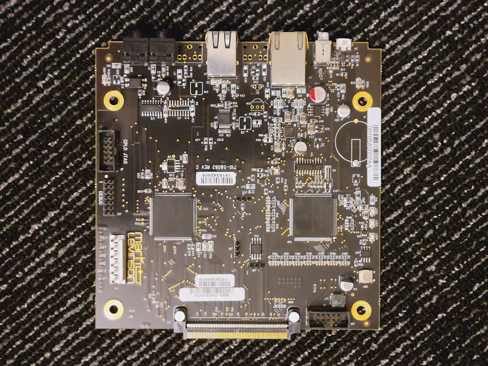
ML-50 Main Control Board
Vibration Mitigation
To further improve the performance of the ML-50 circuits, exterior vibrations are addressed by precisely designed and balanced feet assemblies. These dampen external mechanical vibrations preventing them from entering and impacting the chassis and associated electronics. The foot design even helps with thermal management by raising the bottom of the amplifier to allow increased airflow for the convection cooled venting configuration.
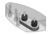
Feet detail with integrated isolation