Tech Talk
Volume Control in Mark Levinson Products
Dimitri Danyuk
Senior Principal Engineer,
HARMAN Luxury Audio Group

Part 1
In its simplest form volume control is a variable resistor or potentiometer.
Potentiometer is a mechanical device that has a long strip of resistive material with a connection on each end of the strip and a third contact - wiper. A wiper can move up and down the length of the resistive strip. One side of the resistive strip is attached to the audio source, the other side is connected to ground and third contact – wiper becomes the output of the volume control.
The quality of potentiometer depends on the quality of the resistive element, the contacts, and the way it’s implemented. Mark Levinson used the best available potentiometers for their products, e.g. Bourns 6657s with rotational [wiper] life of one million shaft revolutions or more.
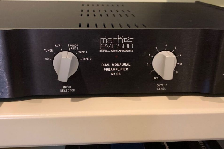
It is not unusual to find the old Mark Levinson product with the mechanical volume control in the perfect working order. The last preamplifier with mechanical potentiometer as a volume control is Nº 26.
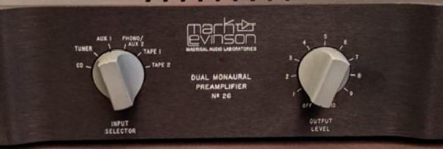
Nº 26 was the last Mark Levinson preamp with potentiometer as a volume control.
Demand to control volume remotely was the main reason to implement electronic volume control.
Mark Levinson engineers chose multiplying DAC for controlling the volume. A multiplying DAC applies a digitally set attenuation to an audio signal, offering almost ideal building block for the volume control.
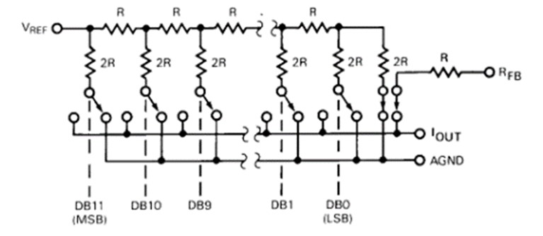
R-2R resistive ladder
Multiplying DAC employs R-2R resistive ladder, shown in figure 2. The resistance ladder provides a digitally controlled output signal by means of electronic switches. Switching transient are minimized because the switches are switching between ground and virtual ground.
Integrated multiplying DAC has the ladder and switches fabricated on a die. On chip ladder resistors provide excellent tolerance and thermal tracking.
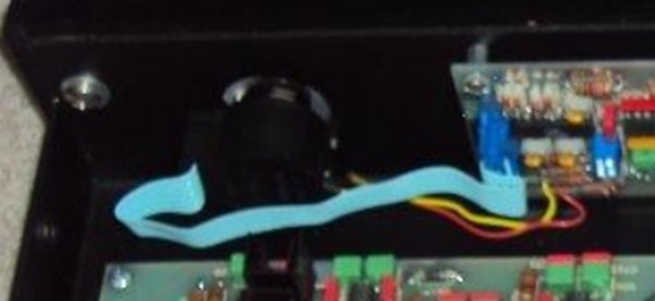
For the first time multiplying DAC was implemented in Nº 28 (DAC8222 from ADI) with control provided by an optical encoder. When the optical encoder shaft is rotated, the encoder sends pulses to a microprocessor, which converts the pulses into the control code for the multiplying DAC.
Multiplying DAC employs R-2R resistive ladder, shown in figure 2. The resistance ladder provides a digitally controlled output signal by means of electronic switches. Switching transient are minimized because the switches are switching between ground and virtual ground.
Integrated multiplying DAC has the ladder and switches fabricated on a die. On chip ladder resistors provide excellent tolerance and thermal tracking.
For the first time multiplying DAC was implemented in Nº 28 (DAC8222 from ADI) with control provided by an optical encoder. When the optical encoder shaft is rotated, the encoder sends pulses to a microprocessor, which converts the pulses into the control code for the multiplying DAC.

Nº 28: The first preamp with multiplying DAC as a volume control.
There are two minor design challenges with integrated multiplying DAC as a volume control: resistance of the R-2R ladder and feedthrough error.
Resistance of the R-2R ladder integrated multiplying DAC is about 10kΩ. That resistance adds thermal noise that can reduce the dynamic range of the volume control.
Feedthrough error is caused by capacitive feedthrough from the audio input to the DAC output (shown below).
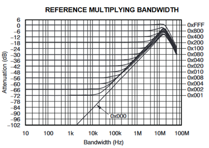
Feedthrough of the typical integrated multiplying DAC.
Some sources e.g. CD-players may have elevated levels of high frequency noise on their output. This noise can pass through the volume control and cause intermodulation distortion in the following stages (power amplifier).
Mark Levinson engineers decided to use discrete components for R-2R ladder. The resistance of the ladder is ten times smaller than typical resistance in the integrated multiplying DACs. This allows to reduce the thermal noise of the ladder resistors and eliminate feedthrough at high frequencies.
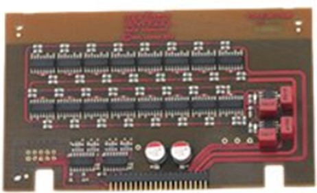
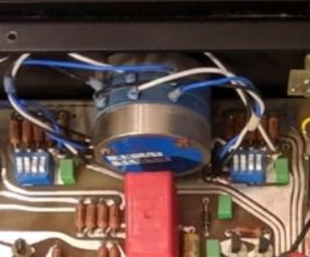
Discrete R-2R ladder board from Nº 52 reference preamplifier.
The first discrete R-2R ladder was implemented in Nº 32 reference preamplifier. Discrete R-2R ladder can be found in Nº 52 reference preamplifier and in most recent products: Nº 526 and Nº 523 preamplifiers, Nº 585 and 585.5 integrated amplifier.
In Part 2 we will discuss volume control implementation in the Mark Levinson 5000 series of products: Nº 5206 preamplifier and Nº 5805 integrated amplifier.
Part 2
The Nº 5206 preamplifier and Nº 5805 integrated amplifier have two independent signal paths: analog and digital.
Analog signal path are fully discrete, direct-coupled, dual-monaural preamplifier circuitry, operating in pure Class A. Digital consist of a built-in 32-bit/384kHz DAC with 4x DSD capable, jitter-elimination circuitry, and a fully balanced, discrete current-to-voltage (I/V) dual-monaural converter. A unique single-gain stage mated to a digitally controlled resistor network for volume control is the important component of the analog signal path.
The heart of the volume control is MAS6116, manufactured by Micro Analog Systems Oy from Finland. MAS6116 is improved version of WM6116, manufactured by Wolfson Semiconductors. (Wolfson ADC/DAC business is now part of Cirrus Logic).
MAS6116 is based on R-2R ladder technology and has unique specifications:
• Gain range from-111.5dB to +15.5dB
• Gain step size 0.5dB
• THD 0.0002% in balanced mode
• SNR 124dB in balanced mode
• Crosstalk -110dB typical
• Input Signals up to +/-18V
• Zero Detection for Gain Changes
• Peak level detector
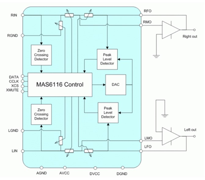
MAS6116 volume control block diagram.
To utilize the richest extent of features in MAS6116, fully custom differential (balanced input and balanced output) amplifier was designed.
That proprietary PurePath circuitry is a foundation of the Mark Levinson 5000 series reproduction capability.
The block diagram of the amplifying block in analog signal path is shown in below.
Key points are:
• The class A input stage is fully symmetrical and converts input voltage into current.
• The output current of the input stage is converted in the voltage by the folded cascode stages.
• The triple output stage isolates the folded cascode output from the load to provide low output impedance.
• The output stage operates in class A and is powerful enough to drive dynamic headphones.
One aspect of the single gain stage is disclosed in US patent 10404222B2 (Bootstrapped application arrangement and application to the unity gain follower).
The details of the operation of the MAS6116 R-2R ladder volume control IC and the single gain stage fully differential amplifier can be found in US Patent 10720895B2 (Fully-differential programmable gain amplifier).
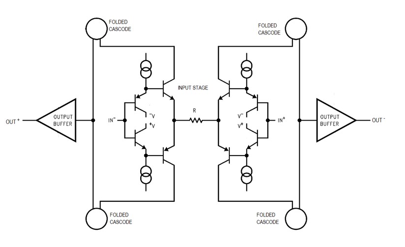
Block diagram of the single gain stage fully differential amplifier.
The volume control in digital signal path is implemented in the digital domain by performing mathematical operations on the digital data representing the audio signal. The volume control is internal to ESS Sabre Pro series 32-bit D/A converter and implemented just before the oversampling filter on the digital data. This allows to reduce the volume substantially without having the quantization errors. Performance-wise 32-bit digital volume control matches analog volume control.
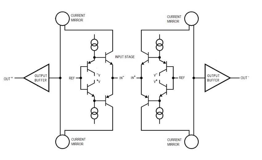
Block diagram of the single gain stage fully differential current to voltage (I/V) converter.
The ESS Sabre Pro series 32-bit D/A converter operates in the current output mode. Current to voltage converter transforms DAC output current in the output voltage.
The block diagram of the fully balanced, discrete current-to-voltage dual-monaural I/V converter is shown in above.
The Class A input common base stage is fully symmetrical and passes the DAC output current to the output stage through the current mirrors. The triple output stage operates in Class A, provides low output impedance, and is capable of driving a dynamic headphone directly.
Mark Levinson engineers continue to pursue best in class practices, components, and patentable techniques in providing the purest results, including the volume control stage.