Tech Talk
Luxury Audio and the Northridge Center of Acoustic Excellence
By Mark Glazer
Senior Principal Engineer,
HARMAN Luxury Audio Group

A major advantage for HARMAN Luxury Audio engineers is the access to the world-class engineering resources at the Center of Acoustic Excellence in Northridge. This Tech Talk describes our amazing test facilities and guides you through the procedures which enable our acoustic engineering team to design best-in-class loudspeaker systems.
Step 1: Test the Transducer Linearity
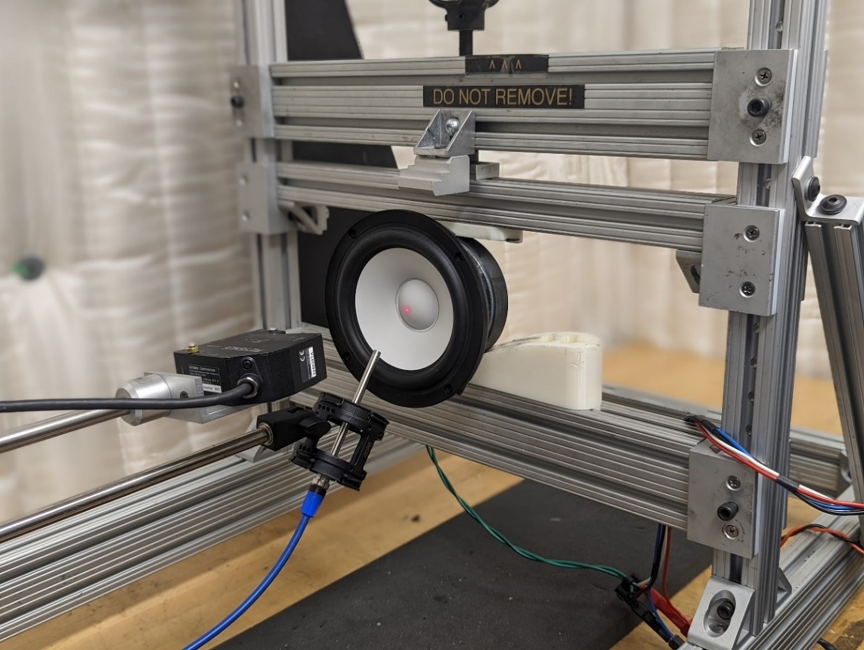
Our acoustic parameter measurement system allows us to examine the linear small-scale movement and the large-scale displacement of loudspeaker transducers. The device under test is first secured on the vise and then a wide bandwidth signal at various levels is applied to it. A laser monitors the displacement of the driver while the analyzer measures transducer voltage and current during the test. In addition, a microphone measures the frequency response.
Some of the important test results are:
1. Thiele/Small values for enclosure design
(Thiele/Small parameters - Wikipedia)
2. Motor flux change from rest position
Go to Page 10: Large Signal Identification (LSI) (klippel.de)
3. Compliance change with displacement from rest position
Go to Page 10: Large Signal Identification (LSI) (klippel.de)
4. Voice coil inductance change versus excursion
Go to Page 11: Large Signal Identification (LSI) (klippel.de)
5. Multi-Tone distortion
Multi-tone Distortion (klippel.de)
6. Transducer temperature change over time
Go to Page Page 11: Large Signal Identification (LSI) (klippel.de)
7. Nearfield measurement of transducer
Near Field Measurement (klippel.de)
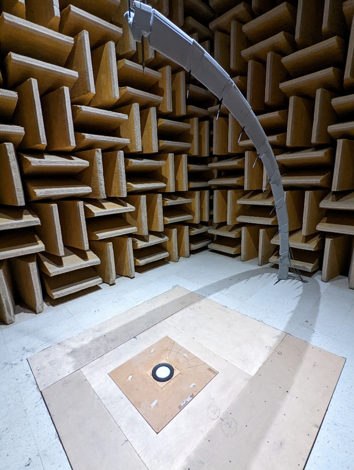
Step 2: Half Space (2pi) Measurement Chamber
A 2 pi (half space) chamber is a critical space for performing accurate ‘echo free’, measurements of transducers and architectural in-wall systems.
Our half space chamber walls measure 18’ L x 18’ W x 17’ H. The walls and ceilings boundaries are completely lined with 1.5-foot commercial fiberglass wedges, to effectively absorb reflections above 100 Hz. The floor has cut outs for all sizes of transducers and in-wall enclosures. This set up provides reflection and diffraction free, repeatable measurements. Above the floor we installed an array of 10 microphones which processes the frequency response measurement sweeps from 0 to 90 degrees.
The device under test is mounted in the corresponding fixture flush on the floor. The microphone array processes the measurements for a thorough frequency response and distortion analysis.
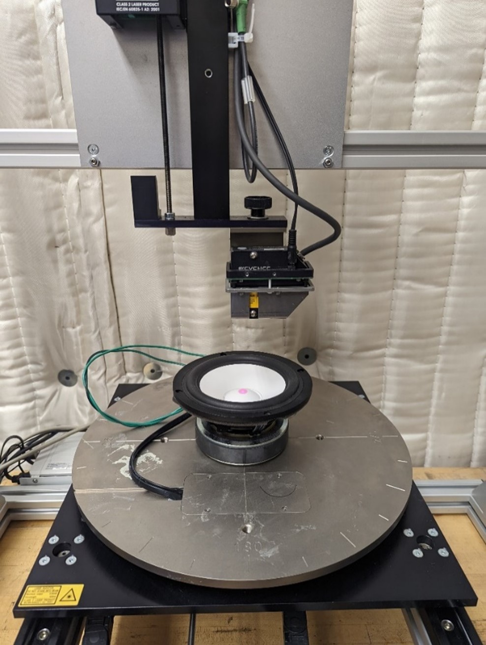
Step 3: Cone Vibration Analysis
Our powerful scanning vibrometer enables us to ‘map’ the surface of the transducer cone and examine the vibrational performance at any frequency. The device under test is mounted on a rotating platform and the laser moves to multiple positions. This test is performed over an extended period. Upon completion, any specific frequency can be retrieved from the collected data. Ideally, the loudspeaker cone should move as a solid unit and not bend or “break up” in its operating range. Now any related issue can be identified and solved by the engineering team.
Technical information can be found here:
AN_31_Cone_Vibration_and_Radiation_Diagnostics.
doc (klippel.de)
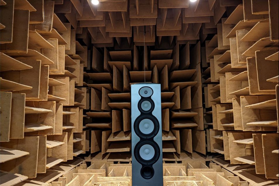
Step 4: Full Space (4 pi) Large Measurement Chamber
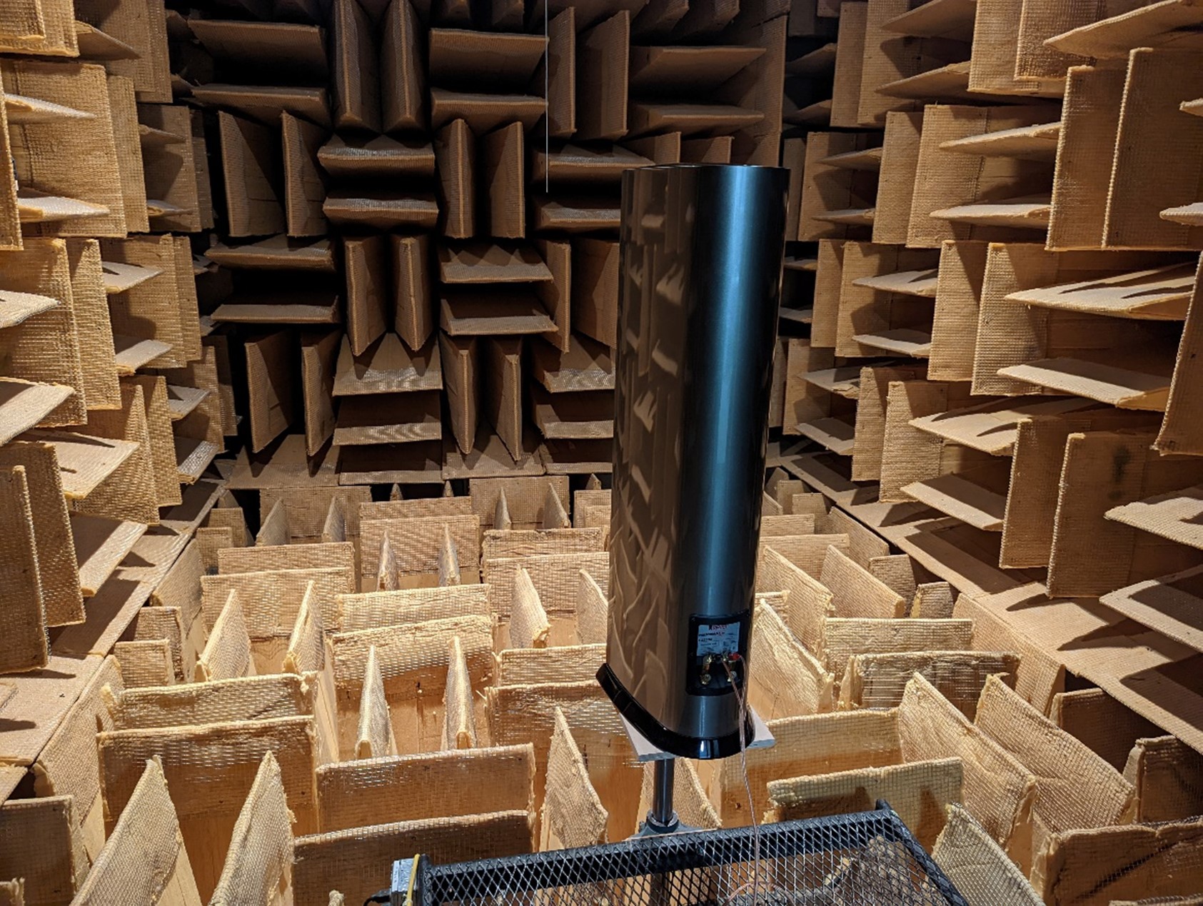
A loudspeaker system emits sounds in a spherical pattern. Therefore, to capture the true measurements of a full range loudspeaker system, a large "echo-free" room, called an anechoic chamber, is required. In addition, the loudspeaker and measuring microphone must be distanced from associated boundaries.
Our large 4 pi (full sphere) anechoic chamber steel isolation shell measures 25’ L x 19’ W x 19’ H. The boundaries are completely lined with 4-foot deep, commercial high density fiberglass wedge acoustic absorbers.
The loudspeaker is placed on a pedestal, which can rotate to any required off-axis angle remotely by computer commands. High resolution measurements for crossover design and finished system analysis can be performed.
Conclusion
It takes a large financial investment and a lot of real estate in providing the tools to be able to engineer great loudspeaker systems. The engineering team at Luxury Audio is fortunate to have these tremendous assets at our disposal.