Tech Talk
Artwork Creation for Mark Levinson Audio Products
By Joe Jagenow
Principal Mechanical Engineer,
HARMAN Luxury Audio Group
Many custom components that are assembled into Mark Levinson audio equipment require artwork to be created. In some cases, the artwork is added to a component for cosmetic reasons, for example a logo or model name, while in other cases we need to apply regulatory markings to a product for compliance purposes.
The process for creating and releasing this artwork to our system of vendors involves many different steps and programs to create precise and attractive graphics that are worthy of the Mark Levinson brand legacy.
First, the component is designed using Solidworks Desktop 3D CAD software. This software ensures that any outlines, holes, or cuts in a part or panel line up exactly with the associated parts that make up a mechanical assembly. For a rear panel design, CAD models will be created or downloaded for each electronic component, and outlines will be made on the part using these CAD models as reference, as shown in Figure 1.
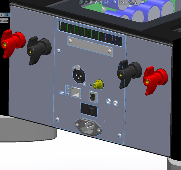
Figure 1: Rear panel layout with label placed into assembly.
These outlines will need to be dimensioned, so that they cannot be inadvertently changed or altered after they have been created. Figure 2 shows an example rear panel, and the various sketch features that define the cutouts and holes in the part.
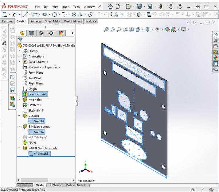
Figure 2: Sketch features define the part cutouts.
Once the part cutouts have been defined the 3D CAD files can be exported to a vendor for manufacturing, but a 2D drawing must also be created to provide detailed specifications for the materials and tolerances for the part. Figure 3 shows an example 2D drawing of a rear panel label component.
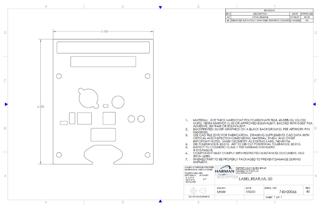
Figure 3: 2D drawing that defines the part geometry and specifications.
In addition to the 2D drawing for the vendor, a separate PDF version of the drawing is created. This drawing is scaled to actual size and contains just the part outlines, as shown in Figure 4. This one-to-one scaled PDF can then be imported into Adobe Illustrator.
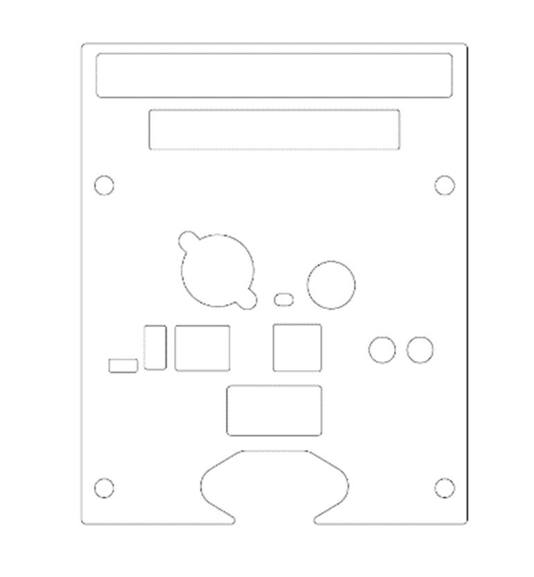
Figure 4: Line drawing used for artwork creation.
Once the artwork file has been opened in Adobe Illustrator, the part outlines can be saved to a layer and used as reference for applying artwork to the component. Illustrator allows for graphic files such as logos or compliance markings to be imported, lines to be drawn, colors to be documented, and different layers of graphics to be separated for printing.
For this example label, we have created a black background, which has been added to its own layer in Illustrator as shown in Figure 5.
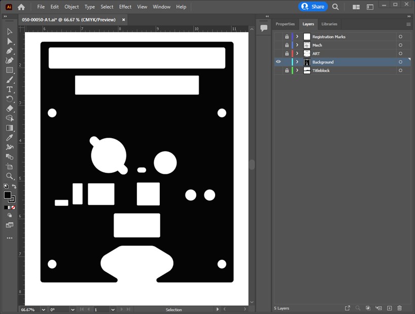
Figure 5: Background layer in Illustrator.
Next, we may need to add the “CE” marking for compliance in the EU, or add text that indicates which cutouts correspond to the inputs or outputs. We can also add markings around the ON/OFF switch, USB and ethernet connectors, and the trigger in/out connectors. Illustrator allows for changes to the font style and text size, as well as alignment of the text to the existing mechanical cutouts. The graphics items can be placed on their own layer in Illustrator, and graphics of different colors separated to unique layers as well, as shown in Figure 6.
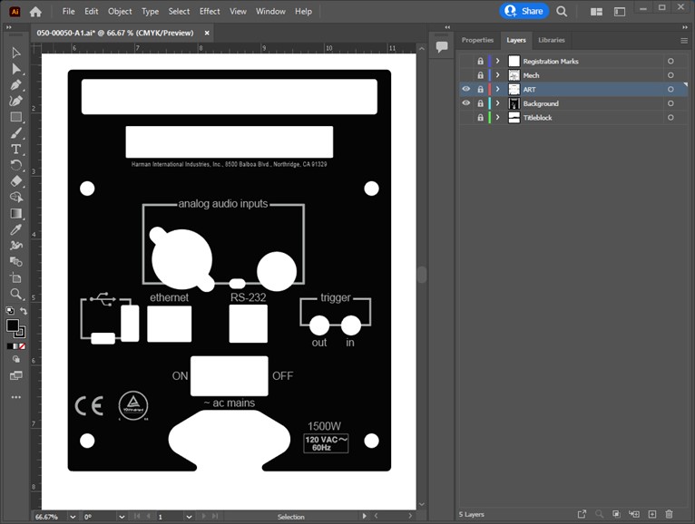
Figure 6: Artwork layers in Adobe Illustrator.
The finalized graphic file receives its own part number, separate from the mechanical part that it reports to in the product bill of materials. This enables a standardized label design to be printed with different artwork files, depending on the top-level part number designation. This reduces development time for new products, by allowing us to reuse label outlines for multiple products. For example the ML-50 rear panel label file shown in Figure 5 has similar dimensions to the No536 rear panel label, but has totally unique graphics applied to the label for this new product.
We will need to provide a version of the artwork file to the vendor, but first we convert any text to outlines. This eliminates the need for a vendor to download specific fonts while preventing any text from being manipulated unnecessarily. We save the outlines file separately from the original artwork file, so internal changes can be made later if necessary. We also export a PDF version of the artwork for the Products team to review, to ensure the text is accurate and meets the product requirements.
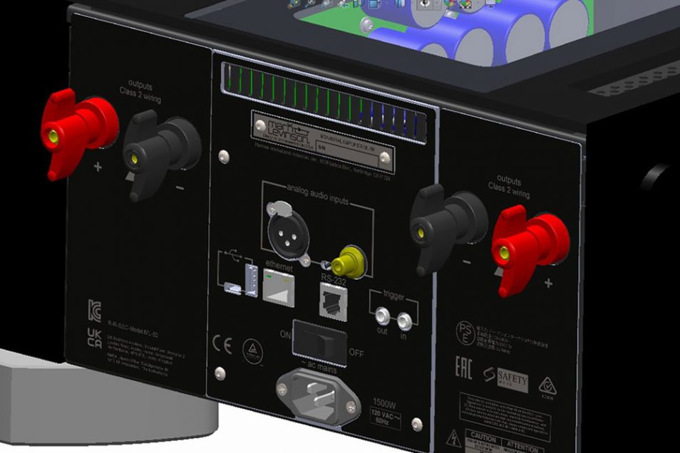
We can also export an image version of the artwork as a JPG or PNG, which can then be imported back into the 3D CAD software. Solidworks has a label feature, which allows for an image file to be mapped onto a part as shown in Figure 7. The image files can also be imported into KeyShot 2D rendering software, for the creation of high-quality renderings that are used in web or print documents.