Tech Talk
The Multi-capacitor Crossover: What is it and what are the benefits?
By Chris Hagen, Principal System Engineer

1. Introduction
A crossover is a necessary component for most speakers. It can be very complicated, splitting the input audio signal into sections by frequency for loudspeaker drivers designed for specific bandwidths. Each “way” could have multiple circuits for not only frequency division, but level adjustment, character adjustments, peak compensation and impedance compensation. It can also be very simple, performing either basic protection or simple frequency response adjustment.
The components used in the crossover are mainly resistors, capacitors and inductors with an improvement path typically in the direction of simply using better parts. This can include using better (or different) materials in the components or using the “better” component as an add-on to the normal part (like a bypass capacitor). Largely, the improvements looked for would be in the areas of improving sonic character, decreasing signal loss, and improving power handling.
Many of the recommendations for improvement come from opinions that may be based on experience with another speaker system but may not truly be a translatable benefit to the system being discussed due to driver and circuit differences. The component type most affected by opinion and unsurety is the capacitor since higher power handling or low inductance resistors and inductors with less distortion can be tested and shown objectively to be an improvement.
One way to remove the opinion and unsurety and objectively improve capacitors is what we call the “Multi-capacitor” or “Multi-cap” circuit. This type of design is more expensive than the single correctly valued part, but makes for a more accurate value for the capacitor, less effective resistance, less power dissipation in the capacitor and distortion performance closer to the component average.
2. Upgrade Crossover Components
Upgrading the components used in the crossover is different depending on the component type. Resistors can be upgraded by going to lower inductance units or higher power-handling models. Inductors can be changed from a ferrite core to a laminated steel core, a powdered iron core, or even an air core. The inductor wire gauge can be increased as well. For capacitors the path has been to improve the dielectric, typically based on perceived affect upon the acoustic reproduction, resulting in replacing electrolytic capacitors with metallized film capacitors, and replacing metallized film capacitors with polypropylene capacitors.
It is worth noting that when changing the conductor or power handling of a resistor, the largest effect will be enlarging the body size, but changing the dielectric of a capacitor or the wire gauge of an inductor will also change the effective resistance (ESR) of the capacitor or the DC resistance of the inductor and can unbalance in level a previously balanced design. So, these changes need to be done in the initial design.
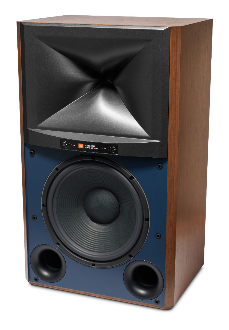
JBL 4349
Most components are produced off-the-shelf at fixed values. It is possible to use two or more of the same type of component wired in series (end-to-end and external connection to the outer ends) or in parallel (one end of each component wired together and then the remaining ends wired together with external connection to the resultant two paired ends) to get different values than those traditionally made, but this is more costly than making the correctly valued part.
Due to this cost, a speaker manufacturer usually produces the individual components so that a component need is satisfied with a single part, although it is possible to see values made up of multiple components.
3. How Does the Multi-capacitor Circuit Approach Work?
The multi-capacitor technique intentionally uses multiple capacitors wired in parallel for a single value. It came about from noticing power dissipation in capacitors: the body moves in response to the applied audio and makes sound – the capacitor “sings”. Considering how stiff a capacitor body can be, this can clearly represent a significant loss of power doing this. This singing by the capacitor is not a big deal as it is inaudible from an assembled speaker system. But the fact that some of the audio signal power is lost in doing this can result in loss of output, dynamics or detail and so it should be minimized.
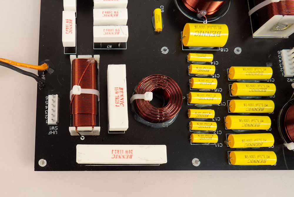
The multi-capacitor technique replaces one large capacitor in a circuit with several small ones that add to the same value. In this way, each constituent capacitor body can be much smaller which would make that body more rigid than the larger one, so less energy would be wasted in movement.
This does make for a crossover that is made up of large quantities of capacitors and so is costly, but the benefits outweigh these issues.
4. More Benefits
Using multiple smaller-valued capacitors also helps by making the overall value more accurate. When one capacitor fills the need, it can vary from one extreme of its tolerance to the other and the value in the circuit is dependent on fortune or expensive sorting. With multiple capacitors, there will be a similar tolerance spread around the value of the smaller capacitors but due to the multiple capacitors averages out and produces a much tighter tolerance combined capacitance.
It also lowers the effective resistance (ESR) for the capacitance position it is used in. This is because capacitors wired this way will reduce the total ESR, dividing the ESR for the smaller capacitor by the number of capacitors used. For example, if a 10-capacitor solution was used for a larger capacitor with an ESR of 0.08 Ohm, but the smaller capacitor had an ESR of 0.04 Ohm, the resultant ESR for the larger capacitor would be 0.04 Ohm/10 or 0.004 Ohm. This is a great improvement considering power dissipation into the capacitor is developed across its ESR.
Lower power dissipation means that there is less power to move the capacitor body. But also, it means that there will be less heat generated in the capacitor itself, so the capacitors implemented as multi-capacitors will not be as susceptible to power-related failure. This lower power dissipation in the capacitor would also mean greater power delivery to the driver. This might exhibit itself in improved detail and dynamics.
Distortion is improved in that if one capacitor is used and it has high distortion, it will be presented at full amount. With multiple capacitors used, the contribution to total distortion of a single capacitor will have no more than 1/n contribution, where n is the number of capacitors used. This greatly diminishes the effect of excess distortion in a capacitor and helps nominalize the resultant performance.
5. Conclusion
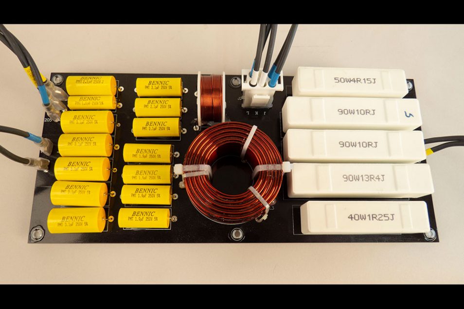
The multi-capacitor crossover approach helps with value accuracy, power dissipation, and signal transmission to the driver. However, it is a costly solution best reserved for models able to bear the monetary cost as well as provide internal space for the boards (see the SCL-1 crossover above, with 34 capacitors comprising the two woofer section capacitors on their own board). However, those who have heard the 4349 or SCL-1 would attest to the sonic quality, making this expensive approach worth it.
Note: The JBL 4349 Studio Monitor uses the multi-cap approach in all series capacitors, whereas the JBL Synthesis SCL-1 uses it for all capacitors. Both systems are highly acclaimed in sonic quality but are also noted for their dynamics. This would be a direct benefit with the type of upgrade described above by using the multi-cap approach in these crossovers.