Tech Talk
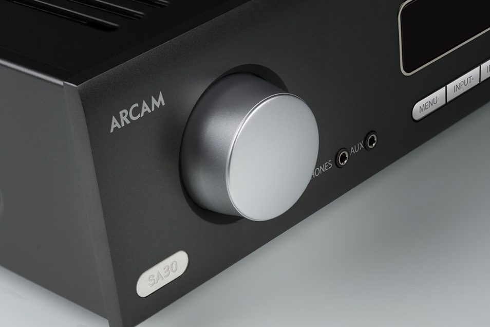
Design Challenges in the Arcam SA30
By Peter Kuell
Senior Principal Engineer,
HARMAN Luxury Audio Group
In the old days of amplifier design a typical 2-channel integrated amplifier would probably have, at most, half a dozen analogue inputs and a couple of pairs of speaker terminals and that was your lot. The electronics inside typically all existed on a single Printed Circuit Board (PCB) and the only wires were there to get the various input and output signals to the physical connections on the outside of the unit.

These days, however, we require a lot more functionality from our integrated amplifiers. The Arcam SA30, for example, has 5 analogue inputs, 4 SPDIF inputs, USB playback, eARC and ARC as well as a full complement of every popular streaming service going.
The number of inputs and the different types of inputs presented several challenges when designing the SA30:
1. Getting all the bits in the box
We are adding A LOT of extra bits of circuitry and quite simply, they won’t fit! We needed to add the following to your standard analogue integrated amplifier design: a Digital to Analogue Convertor (DAC) and its associated output Low Pass Filter (LPF), an Analogue to Digital Convertor (ADC) and its associated input LPF, a network streaming module and a network physical layer convertor for a wired network connection.
2. Keeping the audio stages “clean” and free from interference from the various high speed digital parts of the design
Here we're concerned primarily with the network module but also with the high-speed digital audio data and clock signals used by the DAC and ADC. The problem with digital circuits and high-speed ones in particular, is the rising and falling edges of the signals themselves cause ElectoMagnetic Radiation (EMI). Think of them like a tiny radio transmitter, the problem is all the other traces on the PCBs or internal cables can act like aerials and tune into this radiation which can start causing unwanted audible interference in the amplifier.
3. Keeping the power supplies “clean” and free from any interference caused by the digital electronics
In a similar way to point 2, every time a digital signal switches on or off it requires the power supply to give it a bit of power to achieve the transition. In the case of a digital audio clock this can be happening 50 million times a second! Unless care is taken these power spikes can appear on the power supplies that power the analogue stages of the amplifier, again causing audible interference.
For the last two points it’s a similar effect to when your mobile phone used to cause your speakers to start making a strange morse code kind of noise when you put them near each other. In the case of the SA30 the effect is not as extreme but is highly undesirable!
The simple solution to these problems is to keep all these “noisy” parts as isolated from the rest of the amplifier as possible.
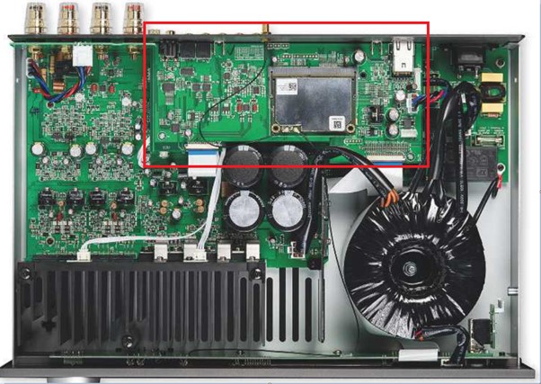
The first thing to do was to increase the height of the box by 10mm. This allowed an extra PCB to be added on which all the all these potential noise sources are fitted. So now it fits in which is a good start!
As well as giving us somewhere to put all our parts the extra PCB has an additional benefit as it is a 4- layer design and as such has a solid ground plane inside it. This solid layer of copper helps to shield the PCB below from some of the EMI generated on the digital PCB. Of course, we need to pay extra for the PCB itself as well as the extra layers, but we needed the PCB anyway and the cost of going from a 2 layer to a 4 layer is minimal if we keep the size of the PCB as small as possible.
For point 3 the digital PCB runs on a completely isolated power supply derived from the main toroidal transformer. This keeps any interaction (and possible interference) between the digital and analogue power supplies to a minimum. The drawback is you need to add extra power supply components rather than just tapping off any power supplies that are already present. This brings with it additional cost and space requirements but in this application the advantages significantly outweigh these drawbacks.
So, for these two points really the only drawback is cost which of course is always a consideration when designing anything, but the benefits it brings are worth the cost. As the saying goes, you can’t go fast for free.
Picture below shows the additional digital PCB mounted above the analogue PCB.
On to point 2. We have made a good start of keeping any unwanted EMI away from our analogue stages by putting a shield in the form of the PCB itself between our digital and analogue stages as well as physically moving the circuits apart and giving them separate power supplies. This is all great but of course the two PCBs cannot work in total isolation, for a start we need to get “clean” analogue audio into the ADC on the digital PCB and “clean” analogue audio out of DAC to the analogue PCB. This is done with Flexi Foil Connections (FFCs) which is straight forward enough. The problem with this is we have effectively created some perfect antennas to catch all that radiated EMI. All of which will be fed directly into the analogue stages. Something we have been actively trying to prevent with our previous efforts!
The solution to this is quite simple but works incredibly well and it’s called differential signaling.
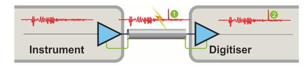
The traditional way of connecting a signal from one point to another is with a single “signal” connection and a single “ground” or return connection, think of this a traditional phono or RCA cable. Signal in the middle, ground round the outside.
The receiver then decodes the signal by comparing the signal level to the ground reference.
The problem with this is that any EMI that gets onto the cable will cause interference on the signal connection but NOT on the ground. So now when the receiver decodes the signal you end up with the original signal PLUS the unwanted interference.
In the diagram you can see this EMI represented by point 1 and it appears at the output of the receiver at point 2.
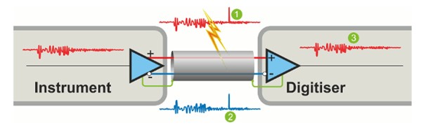
In a differential system we still have our signal and ground connection, but we add another signal connection. This additional connection is the exact opposite (or inverse) of the original signal. Think of this like an XLR cable. In this case the receiver decodes the signal by effectively subtracting the inverse signal from the original signal rather than using ground as the reference.
So, what is the benefit? So far, we have achieved the same signal transmission but used an extra conductor….
The big advantage here is any interference will affect both the original and inverse signal equally. When the receiver then subtracts them from each other the interference cancels itself out resulting in the original “clean” signal being output from the receiver.
In the picture below our interference appears on the original signal at point 1 and on the inverse signal at point 2 Once decoded it is effectively removed by the receiver resulting in a “clean” output at point 3.
In the SA30 we take advantage of this property of differential signaling on the analogue inputs into the ADC and the analogue outputs of the DAC. In practice this means a lower noise floor resulting in increased Signal to Noise (SNR) and no unwanted audio artifacts or distortion appearing in our analogue stages of the amplifier.
The benefits in the case of the SA30 design are massive and the only real drawback with this arrangement is that it requires an additional conductor to carry the inverse signal, so an extra 4 connections in the case of the SA30. As the difference in price between a short 16-way cable versus a short 20-way cable is so small it isn’t even worth mentioning.
So, as it turns out sometimes you really can go fast for (almost) free.