Tech Talk
Getting Chips to Talk, Part 1
By Chris Mann
Principle Software Engineer, Global Engineering
HARMAN Luxury Audio Group
Introduction
Modern audio products include sophisticated components that handle tasks which include streaming, interconnectivity and networking. The functional complexity of these components requires dedicated microprocessor control.

To build a system these microprocessors need to communicate, exchanging information such as settings and data.

In Part 1 of this two-part series we look at the low-level requirements for a communications protocol, and consider the factors involved in choosing the right protocol for the job in hand. We will compare the features of some of the most common communication protocols (UART – Universal Asynchronous Reception and Transmission, I2C – Inter-Integrated-Circuit, and SPI – Serial Peripheral Interface).
In Part 2 we will look at the types of data that are transferred and how the messages used to transfer it are structured.
Getting the information from A to B
Connection between microprocessors is done by connecting the output pins of one microprocessor to the input pins of the other. The voltage over this connection is then controlled by the microprocessors in order to simulate a digital signal (i.e., a signal that is either On (1) or Off (0)).

The digital signal is then converted into a series of bits. Each bit has one of two values 0 or 1. Sequences of bits are built up into messages which are interpreted by the receiving microprocessor and used to take an appropriate action. Within the microprocessor, bits are generally organized into bytes which are comprised of 8 bits. This allows a byte to hold a value between 0 and 255 (28 – 1).
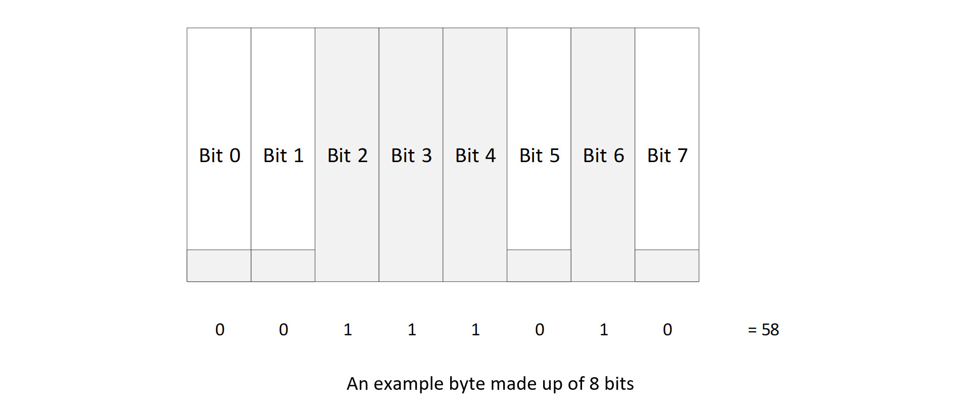
Depending on the type of encoding used, a byte can be used to represent a number, a character (e.g. in the ASCII character set 58 represents a colon ”:”), or a sequence of On/Off values.
Deciding when a bit should be read comes down to the communication protocol being used. For instance, in the example below bits 2 – 4 are all On. In this scenario the voltage over the connection would be consistently high, so how does the microprocessor know that there are 3 bits rather than 1?
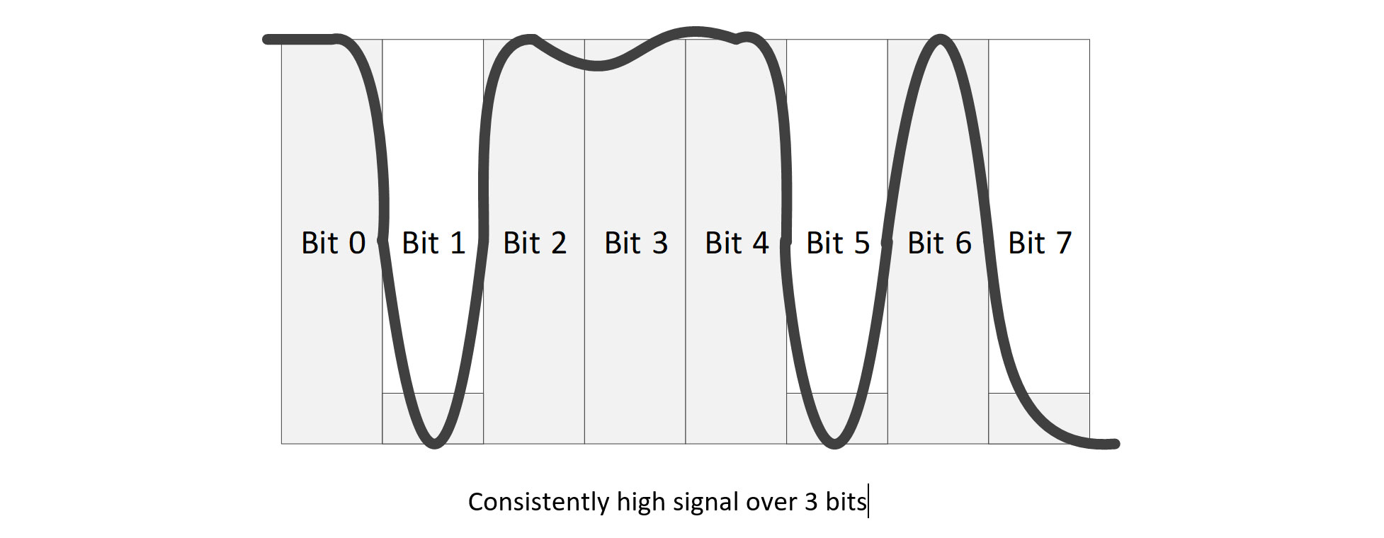
This is achieved in one of two ways:
• The two microprocessors agree on how long it takes to transfer a single byte (hence 3 bits takes three times as long as 1 bit).
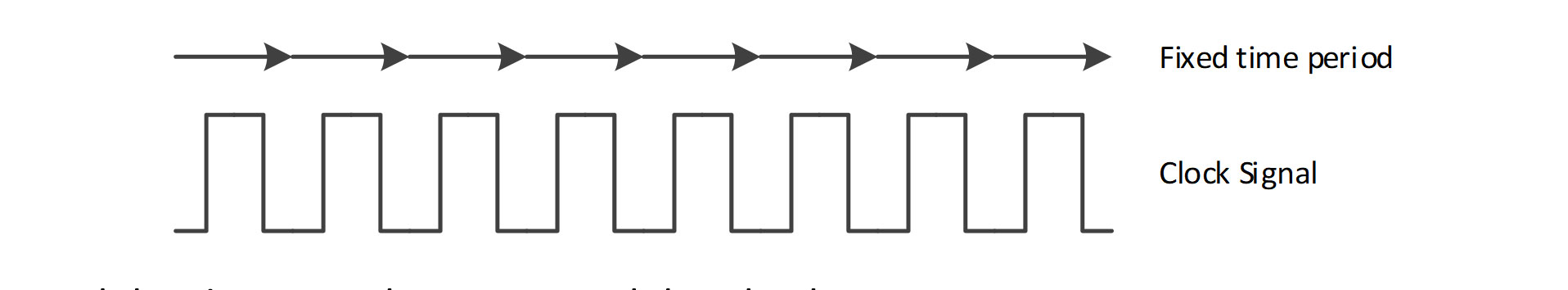
• The communication includes what is known as a clock signal, where a separate communication line sends a regular pulse with each pulse indicating the start and end of a single bit.
Each approach has its own advantages and drawbacks:
The fixed time period approach used by UART means that both ends of the communication need to agree on what the fixed time period is before starting to send information, and to be able to reliably transmit and receive data at that speed. This is defined by the Baud rate of the connection which can be any speed up to around 300kBits/s.
A clock signal requires an extra line of communication (meaning an extra input/output pin on the microprocessor) and an agreement on who will control it; however it has the advantage that the duration of a single pulse can be more flexible than a fixed time period approach, allowing for small fluctuations to be added if required when there are increased loads on the microprocessors. Both the I2C and SPI protocols use this approach, with I2C supporting speeds up to 400kBits/s and SPI up to 8mBits/s.
Who is in charge?
The concept of Primary and Secondary are used extensively in communications protocols including I2C and SPI, where the Primary is responsible for initiating the transfer of a message with the Secondary. It is also possible for a single Primary to control multiple Secondaries over a shared communication bus using an addressing system.
Consideration is required when putting multiple Secondary devices onto a single communications bus, as it is only possible to transfer messages between the Primary and a single Secondary at a time. This means that while it may be theoretically possible to host multiple Secondary devices on the same bus, it may not be feasible if any of the Secondary devices has a particularly “chatty” or time critical messaging protocol.
The clocked approach fits neatly into the Primary/Secondary relationship where it is the Primary that generates the clock signal, and hence controls communication.
Which way is it going and when?
A consideration when thinking about communication protocols is what direction will the messages be transferred and when.
Where a microprocessor is controlling peripheral devices, often the transfer of information is one way (microprocessor to peripheral). This is known a Simplex communication.
Where two-way communication is required, there are two choices: Full-Duplex where messages can be transferred in both directions simultaneously, and Half-Duplex where messages can still be transferred in both directions but only in one direction at a time.
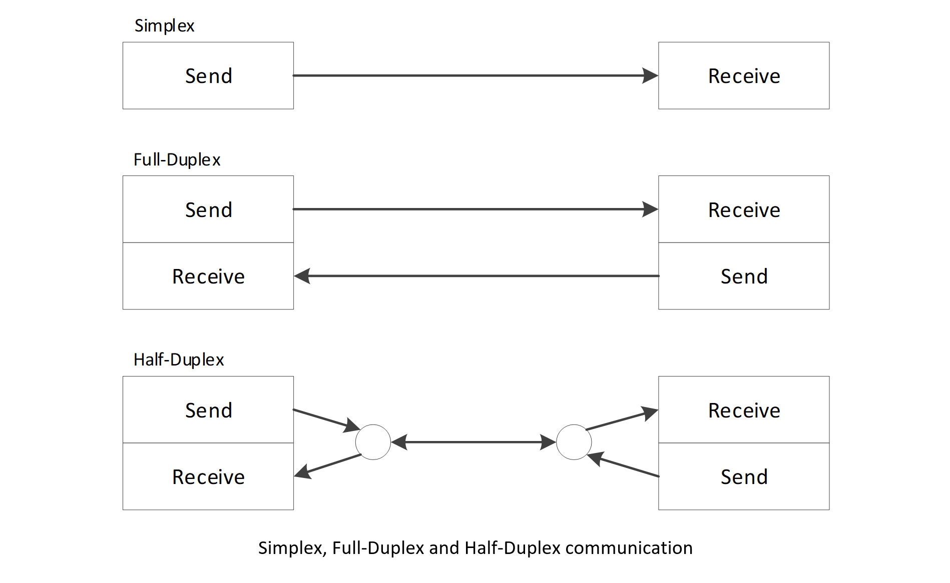
RS232 can support any of these approaches, whereas I2C will only support Half-Duplex and SPI Full-Duplex.
How many pins have you got?
One of the considerations when choosing which communications protocol to use is the availability of output and input pins on the microprocessors involved. A given model of a Microprocessor chip will have a fixed number of pins used for connections with other microprocessors and peripherals.
A further limitation occurs where the pins have dedicated functions. For instance, the Microchip PICMZ2048EFM144 has 144 pins but only supports 6 UART, 4 I2C and 2 SPI connections.
The different communication protocols each have differing requirements for the number of pins and communication lines required.
UART
A UART only requires 2 lines for 2-way communication. Each line transfers data in a single direction which allows it to run in Simplex, Half-Duplex or Full-Duplex modes.

I2C
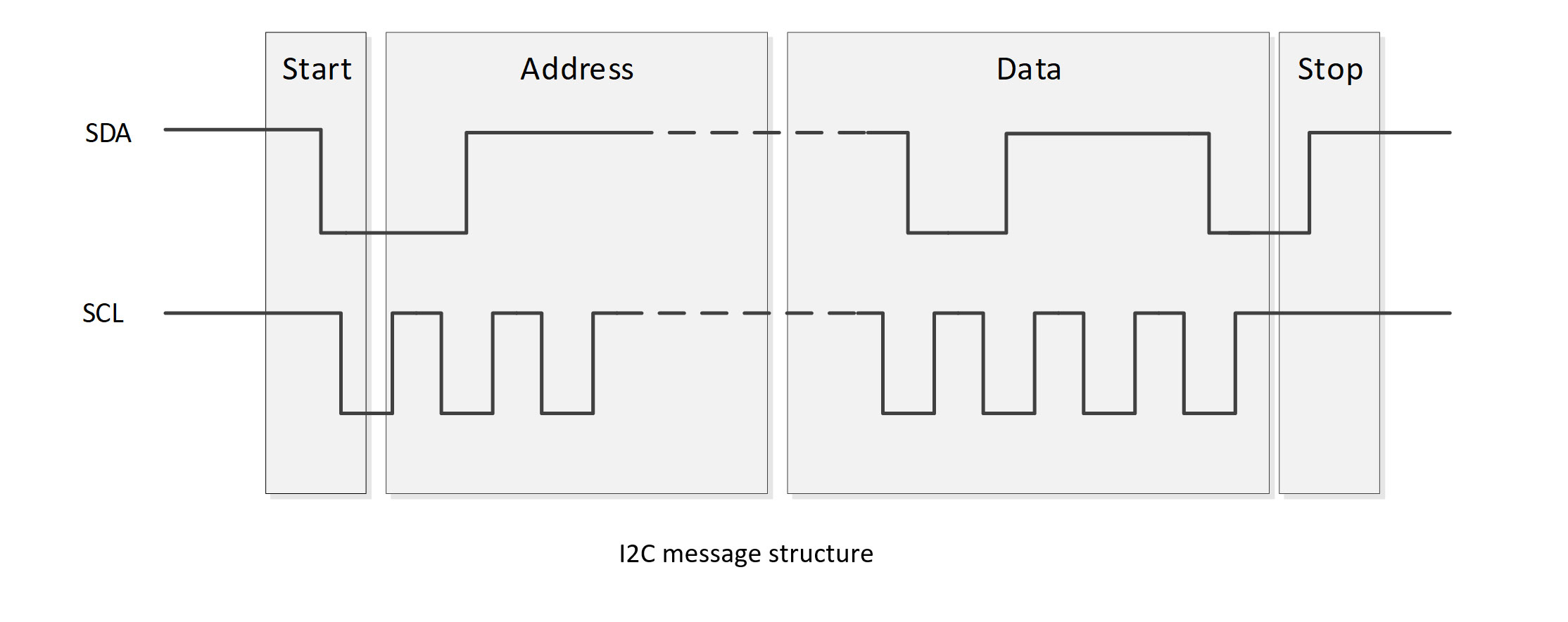
I2C requires only 2 lines for communication. The SDA line carries the data and the SCL line provides the clock signal. Where the communication bus supports multiple Secondary devices the choice of which Secondary to use is controlled by an address included in the data transmitted. Each Secondary must have a unique address for this to work.
The protocol does not include a mechanism for the Secondary to be able to initiate sending data to the Primary, so where this is required an external mechanism (such as raising an interrupt on another pin) is required for the Secondary to request that the Primary initiate a message that allows the Secondary to transmit data.
SPI
The SPI protocol requires 3 lines for data communication plus a further line per Secondary device to enable the selection of the Secondary, as unlike I2C, there is no addressing included in the data transmitted.
What’s in a message
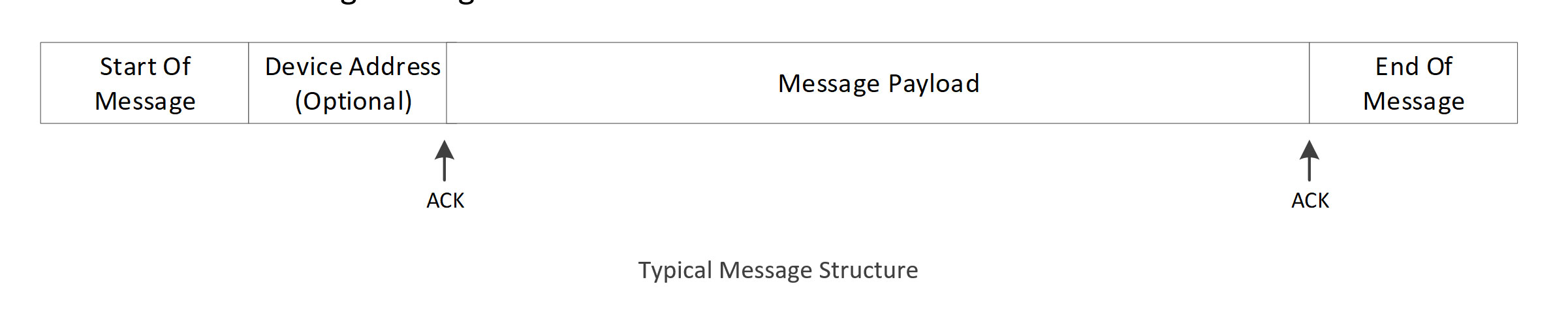
A typical message will be built from the following components:
Start of Message Indicator
This is used to indicate that a new message is about to be sent. In general, this is indicated by a change in the state of the lines that does not occur during message transmission. For example, with I2C a start of message is indicated by the SDA line switching from High to Low while the SCL line is High (when transmitting data it only changes when the SCL line is Low).
Device Address
In communication protocols such as I2C that support multiple Secondary devices the first part of the data transmitted is the address of the Secondary device. Each Secondary device will have a unique address and will use it to decide whether the message is intended for them. In general, it will inform the Primary device that it is ready to receive the message payload by sending an acknowledgement (ACK) back to the Primary on receipt of the address.
ACKs and NACKs
ACKs and NACKs are used to ensure that the message data has been transferred successfully. An ACK is sent by the device receiving data to indicate to the sender that it has received the message and can process it. A NACK on the other hand is used to indicate that the message is somehow corrupt and should be re-sent.
Message Payload
The Message Payload contain the data to be transferred in the message. This can be as simple as a few bytes or a highly complex structured message.
End of Message Indicator
Like the Start of Message Indicator, the End of Message Indicator is used to indicate that the message has completed. Again, this is generally indicated by a change in the state of the lines that does not occur during message transmission.
Conclusion
There are a number of choices to be made when selecting the type of communication protocol to be used for transferring data between microprocessors, and often this is dictated by the hardware as much as the requirements of the software.
In Part 2 we will look at the types of data that are transferred in the message payload and go into the design of a messaging protocol.