Tech Talk
JBL HDI-1200P Subwoofer and Class D Amplifiers
By Armando Martinez – Distinguished Engineer

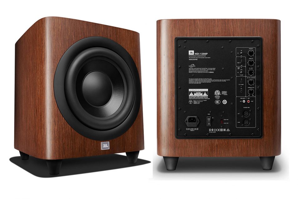
The JBL HDI-1200P 12-inch Powered Subwoofer is a 1000W (RMS) system designed to operate over a wide range of mains voltages in order to have a single amplifier solution for the many worldwide regions supported by Luxury Audio. There are many choices in amplifier and power supply topologies to meet the requirements and every single one of them offers benefits, but also challenges. In this case, considering the capabilities derived from the entire system, it was decided to use the combination of a highly efficient SMPS (Switch Mode Power Supply) and the amplifier topology that can provide the highest level of dynamics over the specified input voltage range; hence the decision to use a Class D amplifier in this project.
Class D amplifiers, also known as Switch-Mode amplifiers, have become the amplification topology of choice for many new systems. Similar to SMPS, they are highly efficient and have a high power density, covering a wide range of applications that go from battery operated systems to high power systems. In addition to their use in powered subwoofers, Class D amplifiers are also spreading into high performance, audiophile-grade amplifiers due to significant advances in how this topology is implemented. At HARMAN, we believe that every solution/topology has a particular place and are always striving to bring the most appropriate solution for the intended application, and this philosophy applies to every single product we make.
Expanding a little bit on switch-mode power supplies and Class D and the why behind them
Most everybody is familiar with the benefits derived from switching topologies, where Class D amplifiers work on the same principle as a switch-mode power supply, with the difference that output voltage is dynamically fluctuating over time.
The key word here is Energy. Normally, amplifiers are rated in Watts, where Energy brings one more variable into the equation, Time.
Energy = Power x Time
What makes a switching amplifier or power supply different from conventional Class A/B linear amplifiers is that they are designed to precisely control the transfer of the required energy at any specific point in time.
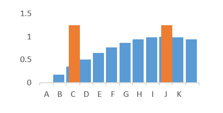
A simple way to visualize this is that the waveform is broken into segments, and in this example, for simplification purposes we are using a sine wave with a peak amplitude of 1V.
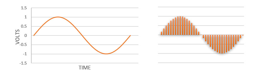
A switching amplifier in principle does something similar, which is breaking or partitioning the signal in small segments, those time intervals are defined by what we call the switching frequency.
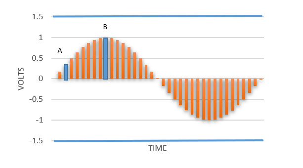
Let’s stop time to see how the system works, to reproduce points A & B as shown as blue vertical lines in the chart above, as we can tell the areas under the curve differs in amplitude, imagine that everyone corresponds in size to a specific bucket.
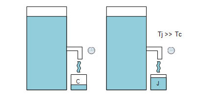
Now imagine that we are filling those buckets from the same water supply represented by the blue lines, at the top and bottom of the chart. To fill the small bucket it will require less TIME than when filling the large one.
This is where the term Modulation comes in place, which is controlling how long we keep the switch (or water supply) closed or the switch (or water supply) open, since we are moving across the envelope of the music signal, in this case represented by the sine wave, the size of the bucket to fill is continuously changing. The amplifier is dynamically adjusting the conduction time to fill the bucket, and the key element here is that the required amount of energy is exactly delivered at the time it is needed, and this is what makes this topology far more efficient than other topologies.
In summary, any switching topology, either amplifiers or power supplies, work on the principle of controlling the amount of energy required at those precise instances. Some time ago a person asked, what would be a good analogy to switching power conversion platforms, a simple answer could be fuel injection used in modern internal combustion engines. Compared to the old carburetor method that continuously draws in fuel by vacuum, the injector is kept open (actively spraying fuel) for only the time that is required to provide the optimum fuel for combustion based on measuring all the variables involved in the combustion process.
With Class D amplifiers, the output voltage is continuously monitored to adjust the conduction time so the output voltage follows the input signal, with a predetermined gain derived from the control loop.
Modulation
Now expanding a little bit more, the term modulation is connected to the conduction time according to the signal level that is being reproduced, meaning the carrier frequency is modulated accordingly. This goes back to the concept of just delivering what is needed, so as an example in the following figure, the orange column represents the energy available and in excess of what is needed.
Let’s take again the water flow analogy filling the containers:
The figure at left represents the signal in blue and the available stored energy in orange.
If using points C & J and following the containers analogy, we find that we have different water supply needs between C & J, but we do not have a way to control water flow pressure other than either opening or closing the valve, which is one of the points that differentiate between Class D and linear type amplifiers. In order to get the water supply needed at every point in time, the only option for us is to close the valve when the bucket reaches the required level.
Moving across the signal or the required water supply, the valve closes and opens at time intervals that give us the required level of water. This type of event is what is called pulse width modulation, which is nothing else than continuously varying the ON time to control the required supply at the load.
Valve ON time in point C is much smaller than the time in point J, where the required level at the container is much larger.
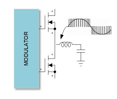
The modulator is just one part it. The filtering and control loop play a significant role in the amplifier performance, and there are different modulation techniques and also output filtering stages which have become more linear. At the same time, control loops are now changing the performance landscape in Class D solutions, with superb linearity and dynamic range.
While this talk has concentrated on the amplifier, it should be emphasized that the amplifier is just one part of the equation and the rest of the components in the system are as important, hence the importance of taking a complete system design approach.
The performance of the transducer, the size of the cabinet and the port tuning play an enormous role in the performance derived from the total system, and in this case the driver was designed with the amplifier capabilities in mind to work together to achieve the desired results.
This design is an evolution over previous designs in the same category, as it met the goal of a single high power amplifier that works across all the global voltage variances, where in the past three or four different amps/SKUs were needed. It will serve as a benchmark for subsequent designs.
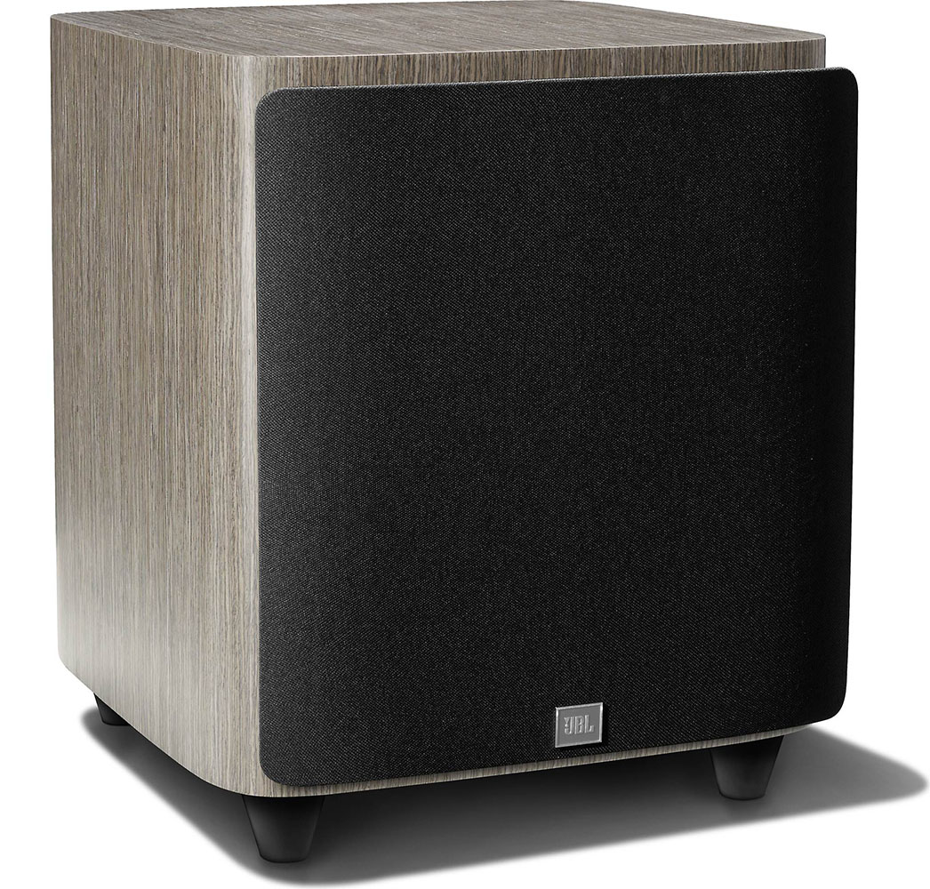
We invite you to listen and experience the difference the JBL HDI-1200P makes when all system components work in unison.