Tech Talk
How Science Improved the Art of the No5302 Amplifier
By Todd Eichenbaum, Director of Engineering and Dimitri Danyuk, Principal Engineer
HARMAN Luxury Audio
Todd Eichenbaum
Because Mark Levinson amplifiers are fully discrete designs built from individual transistors, resistors and capacitors, the requirements of the amplifier — its power rating, its target cost, and the sound we want to achieve — drive literally hundreds of design decisions. An amplifier’s sound is dependent to varying degrees on every aspect of its design. Which transistors did we use and at what amount of bias current are they operating? Which topology did we use for the voltage gain stage, and which for the output stage? What sizes and types of resistors did we select and how capacious is the power supply? In this article, we will discuss how we chose the amount of gain and negative feedback in the No5302 and how we selected resistance values to realize that.
An ideal amplifier is often described as “a straight wire with gain.” In other words, the signal at the output of the amplifier should be exactly identical to the signal at the input, but larger. In reality, amplifiers add distortion, they limit bandwidth and they exhibit variations in gain depending on the load connected to them. For years, engineers have adjusted amplifier performance by employing negative feedback, which sends a portion of the output signal back to the input through a network of resistors and capacitors — effectively a scaled replica of the output. The amplifier then subtracts the feedback signal from the input signal and it uses that difference in signal to fix errors in the output signal. Adding negative feedback decreases the overall gain of the amplifier, but it trades that extra gain for reduced distortion, wider bandwidth and lower output impedance — all good stuff, right?
Well, maybe. Negative feedback has been a source of discussion among audiophiles and engineers for many years. Some designers see it as a panacea, able to deliver amplifiers with nearly immeasurable distortion, while others eschew its use completely, arguing that in any amount it sounds unnatural. We believe that negative feedback can be a useful tool, but only when properly and judiciously applied to an amplifier that already works well without it.
We start by defining the open-loop and closed-loop gain of the amplifier. The loop in this case is the negative feedback loop: open-loop gain is how much gain the amplifier has without negative feedback and closed-loop gain is the final amount after the negative feedback is applied.
We also adjust the open-loop bandwidth of the amplifier, because this, combined with the negative feedback used, affects the amplifier’s stability and transient response. Real-world amplifiers do not have infinite bandwidth, so it takes a small but finite amount of time for the input signal to get amplified and come out the other end. The negative feedback signal is therefore delayed relative to the input, which can lead to problems as the feedback tries to fix the amplifier’s behavior at higher frequencies — one example of why feedback must be applied prudently.
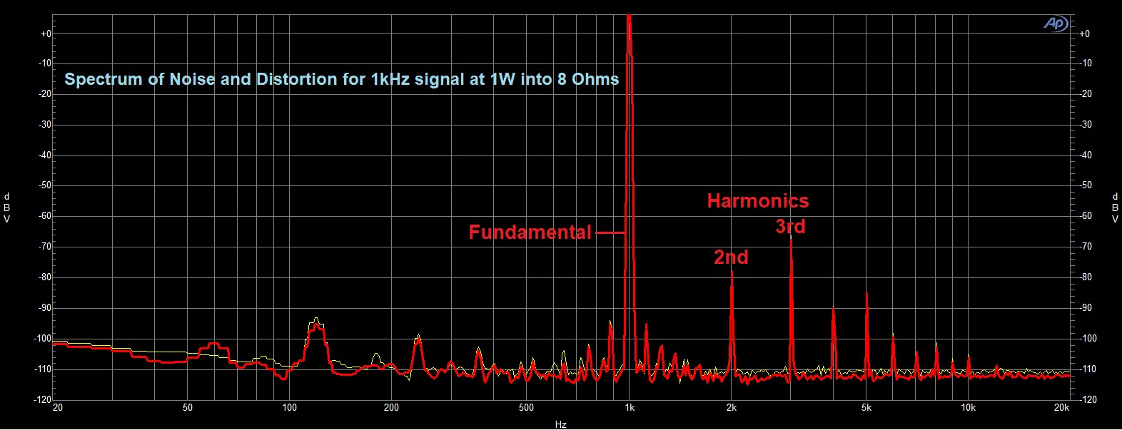
Figure 1: Spectrum of noise and distortion for 1 kHz output signal at 1 W. Note the dominant harmonics are second and third; we believe this offers sonic benefits.
Our earliest version of the No5302 amplifier had 26.5 dB of closed-loop gain — a common value for Mark Levinson amplifiers — and just over 80 kHz closed-loop bandwidth. (26.5 dB corresponds to a gain of roughly 21x, i.e., a 1V input signal results in a 21V output signal.) Total harmonic distortion with an 8-ohm load measured around 0.02% at 1 kHz and 0.2% at 20 kHz, and the predominant harmonics were second and third. (See Figure 1.) Open-loop gain was around 40 dB, so the amplifier was achieving very respectable measurements with a modest 13.5 dB of feedback. Nearly all these numbers were in line with our initial design goals, although we decided to try to squeeze out a bit more high frequency bandwidth to mitigate a very subtle subjective harshness in the treble.
There were many different methods that we could employ to increase the closed-loop bandwidth; however, the trick would be to do so without significantly increasing the distortion, changing its “signature” (predominantly second and third harmonics) or negatively affecting the subjective sound quality. Good engineering is all about managing design tradeoffs, and that was how we approached this challenge.
In this case, the open-loop and closed-loop gain of the No5302 are determined primarily by three sets of resistors. (Note that this is not a universal rule for all amplifiers, but, rather, a function of the circuit topology of the No5302.) The first set determines the signal current through the input stage, the second set determines the open-loop gain of the amplifier (roughly the ratio of the second and first sets of resistors) and the third set determines the amount of negative feedback (inversely proportional to the ratio of the third and first sets of resistors).
Option 1 was to increase the open-loop gain by increasing only the value of the second set of resistors. Since we would be holding the closed-loop gain constant, this would increase the amount of negative feedback, which in turn would widen the closed-loop bandwidth.
Listening tests revealed subjective improvements in the smoothness and clarity of the treble. Although the overall size of the soundstage was similar to the original design, placement of images within the soundstage was vague, with poor front-to-back definition and less ambient information. As superb imaging has always been one of the hallmarks of the Mark Levinson sound, this was not a good result.
Option 2 was to increase the open-loop bandwidth, thereby increasing the closed-loop bandwidth, which we did by decreasing the value of the second set of resistors (the exact opposite of Option 1). In conjunction with keeping the output capacitance of the voltage gain circuit constant, decreasing the resistance here increases the frequency of the low-pass filter effectively formed by this resistor-capacitor network. Of course, decreasing the value of the second set of resistors also decreases the open-loop gain, which in turn reduces the amount of negative feedback for unchanged closed-loop gain.
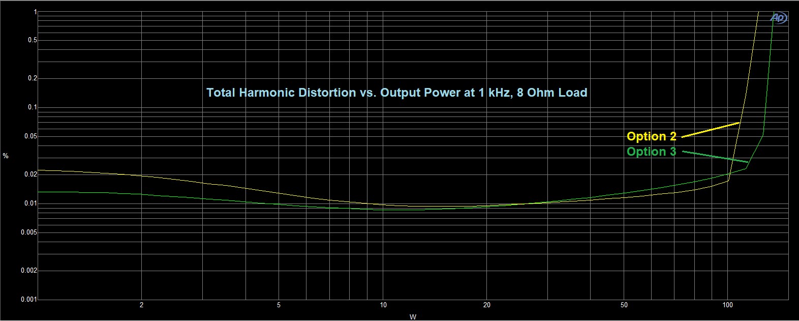
Figure 2: THD + noise vs. output power. Note the rise in THD immediately above 100 W for Option 2, whereas Option 3 maintains lower THD at higher output power.
Listening tests revealed an extraordinarily large, layered soundstage, in addition to similar improvements in the treble noted in Option 1. When listening to dynamic material at high levels, however, the amplifier sounded noticeably less powerful. A distortion sweep, measured relative to output power, showed a “knee” in the curve at much lower power than before — clearly an undesirable result which outweighed any improvements in the soundstage. (See Figure 2.)
Option 3 was to increase the open-loop bandwidth without decreasing the open-loop gain, which we did by simultaneously and proportionally decreasing the values of all three sets of gain-setting resistors. (See Figure 3.) Doing this was a bit of a juggling act, though: if the resistor values were too small, they would draw too much current from the voltage gain circuits, which would cause a notable increase in harmonic distortion.
Listening tests revealed this to be an optimal solution. The additional high frequency bandwidth — now nearly 120 kHz — yielded subjective improvements in smoothness and openness in the treble, while the feedback ratio helped the amplifier maintain performance at high power without adversely affecting image width and depth. In fact, in combination with a subsequent adjustment of the DC servo to extend and flatten the amplifier’s low-frequency response (a topic for another article, perhaps…), the width, depth, and layering of the soundstage closely approached Option 2 but without any of that option’s drawbacks.
In the end, we proved to ourselves once again how the gain structure, bandwidth and amount of negative feedback all contribute to multiple aspects of an amplifier’s sound. By applying a methodical, scientific approach, we were able to improve not only the amplifier’s measurements, but also its imaging, staging and treble clarity — just one example of how science meets art in the Mark Levinson No5302.
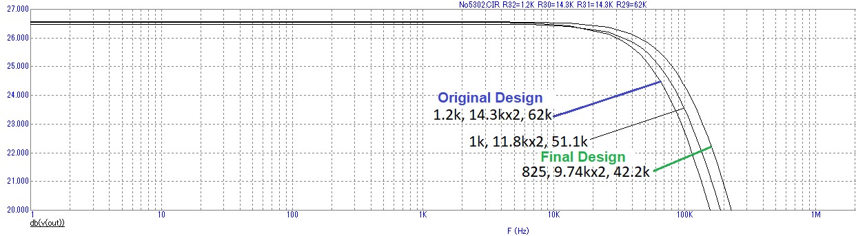
Figure 3: Gain vs. frequency simulations for three different resistor combinations. Bandwidth is defined as the frequency at which the gain is reduced by 3 dB relative to its maximum value; here that point is 23.5 dB. Option 3 extends the bandwidth to nearly 120 kHz, compared to just over 80 kHz originally.