Tech Talk
Part Creation in 3D CAD –
How SolidWorks Works
By Matthew Mantle – Senior Mechanical Engineer, Arcam

To complement Mr. Waterman’s excellent article about how we Mechanical Design Engineers "do our thing" (Mechanical Engineering for Mark Levinson), what follows is a brief summary of how we use 3D CAD. In our case it is SolidWorks software, but most 3D CAD packages operate in a similar way.
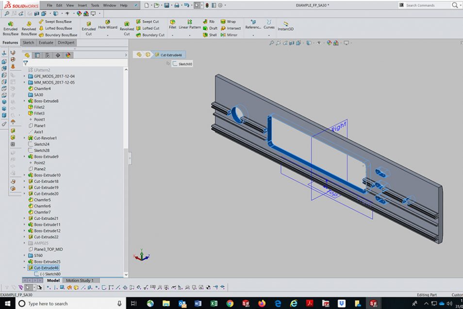
The usual starting point is a 2D sketch. The 3D environment contains an origin point and three perpendicular planes labelled Front, Top and Right by default (Fig.1). First the designer picks a plane appropriate to the part orientation, e.g. Right for a Front Panel (not Front – see below!), or Top for a Chassis Base. Simple tools enable the outline or cross section of the part to be drawn (sketched), then dimensions are added to define the exact size and proportions.
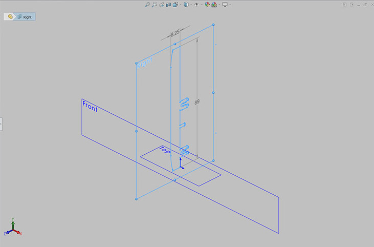
Fig. 1
From this there are four main types of solid parts that can be created: extruded, turned, moulded and sheet metal.
Fig.2 shows the Arcam SA30 Front Panel as an example of an extruded part, the sketched profile is the cross section, which is extruded to create a solid part of the specified length. This is the reason for using the Right plane for the initial sketch, as it is perpendicular to the extruded direction.
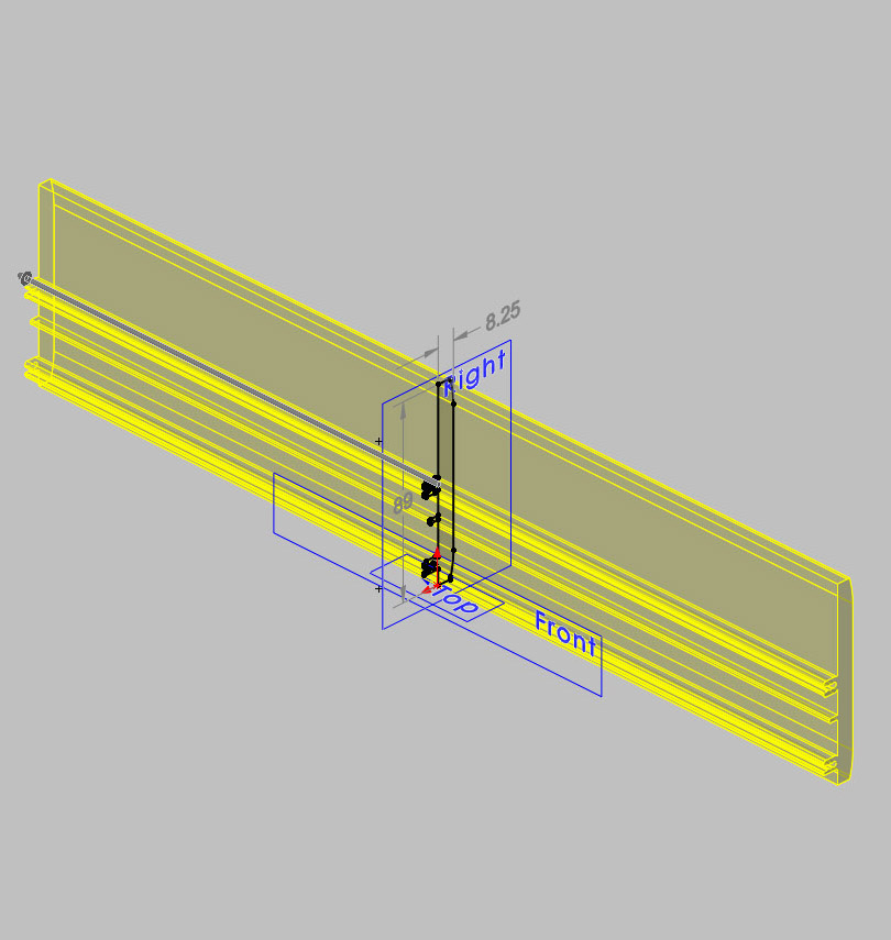
Fig. 2
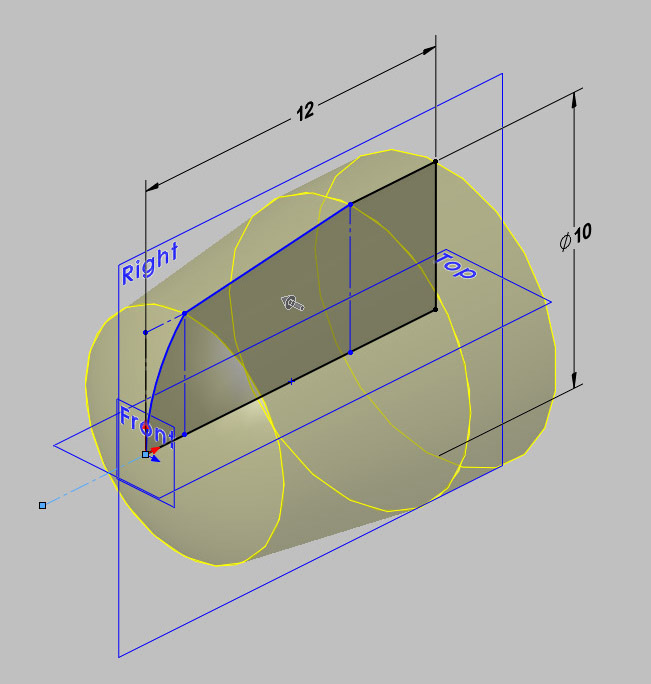
Fig. 3
Turned parts can be created by sketching the longitudinal profile (outline) and rotating it about an axis (Fig.3). Solid part or thin shell options are available from an aluminium button machined from solid, or a thin-formed aluminium cap for a volume control knob.
The next stage is simulating machining of the part features. Sketches are created on different faces of the extrusion, defining areas of material to be removed (Fig.4). The Cut facility is used to remove material to a specified depth (e.g. fixing holes and mounting faces), or straight through the part (e.g. openings for buttons & windows). This matches the actual manufacturing process, so in theory the created CAD part should be realistic!
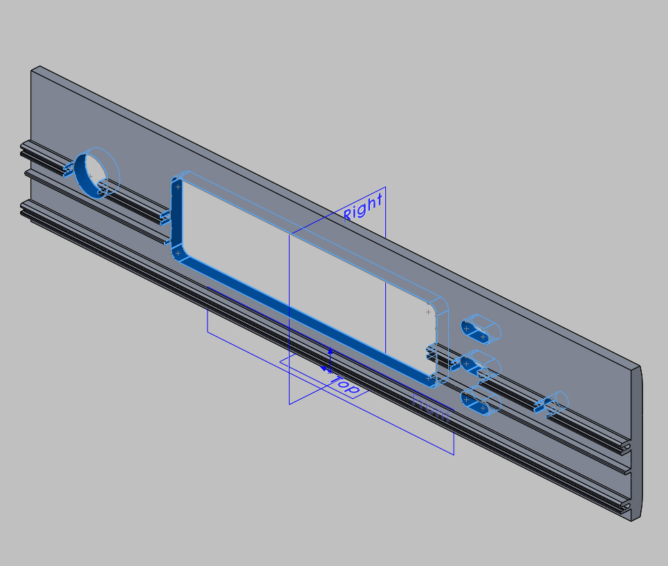
Fig. 4
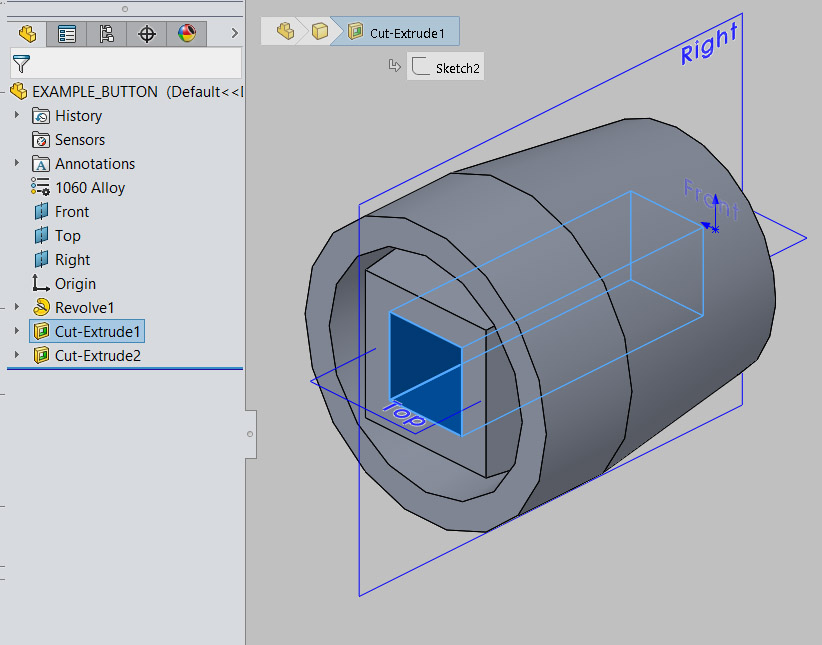
Fig. 5
SolidWorks saves a "design tree" which details all the operations (in order) carried out to create the part (Fig.5). If a dimension is changed in an earlier operation, this change is carried forward through all the other operations to change the finished part. This is where simplicity is key. Complex parts with many operations are more difficult to modify earlier in the ‘design tree,’ often resulting in errors when dimensions or features clash later on. Sometimes these can only be rectified by recreating the part again from scratch – a time-consuming process.
It is possible to add material using further extruded sketches on different faces. This typically results in a moulded part, either a plastic moulding (e.g. SA30 plastic button assembly) or a metal casting (e.g. Solo Uno cast aluminium cover, Fig.6).
Moulded parts can also be created from 3D surfaces. These are often imported from other systems (e.g. Industrial Design software) or defined using some of the more sophisticated CAD tools available in SolidWorks. By their very nature they are far more complex. They are best avoided wherever possible (for the reason detailed above), as modifications are more likely to cause errors requiring part recreation.
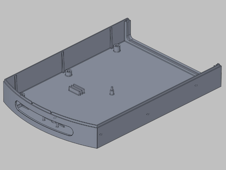
Fig. 6
On all moulded parts, the Design Engineer needs to consider the location of the split line. This is the face or faces about which the mould tool sections will come apart to enable the moulded parts to be released. This has many implications, including the aesthetics of the part (as a moulding mark will be visible) and the location of drafted faces.
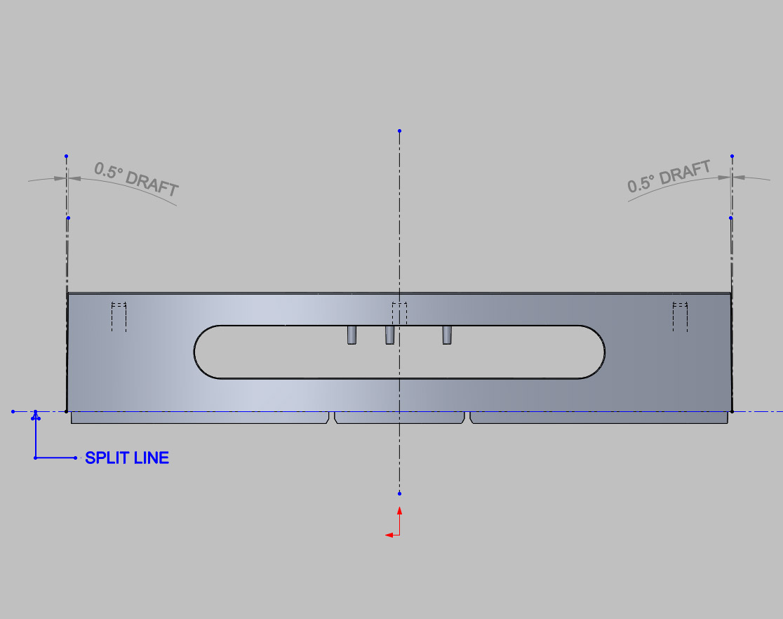
Fig. 7
Adding draft is another cause of complexity. This is the slight taper required on faces parallel to the direction of ‘pull’ of the mould. It is usually only a few degrees but is vital to ensure the part will release from the mould without getting stuck (Fig.7). Adding draft is best left to the end of the ‘design tree’ where possible as it can cause errors if earlier operations are changed.
Alternatively, many suppliers utilise their own mould creation software which will add appropriate draft angles where required. These will be optimised for the machines and material they use. In this case it is simpler to leave the part un-drafted. However, the supplier must understand which faces are critical and should not be changed by the addition of draft e.g. the front of a moulded button should be as-designed so it fits closely in the hole in the Front Panel, but it may be acceptable to taper the unseen rear.
SolidWorks provides several mould checking tools (e.g. Draft Analysis) to help ensure the part is manufacturable. Any omissions by the Designer (e.g. faces requiring draft) are clearly highlighted (Fig.8).
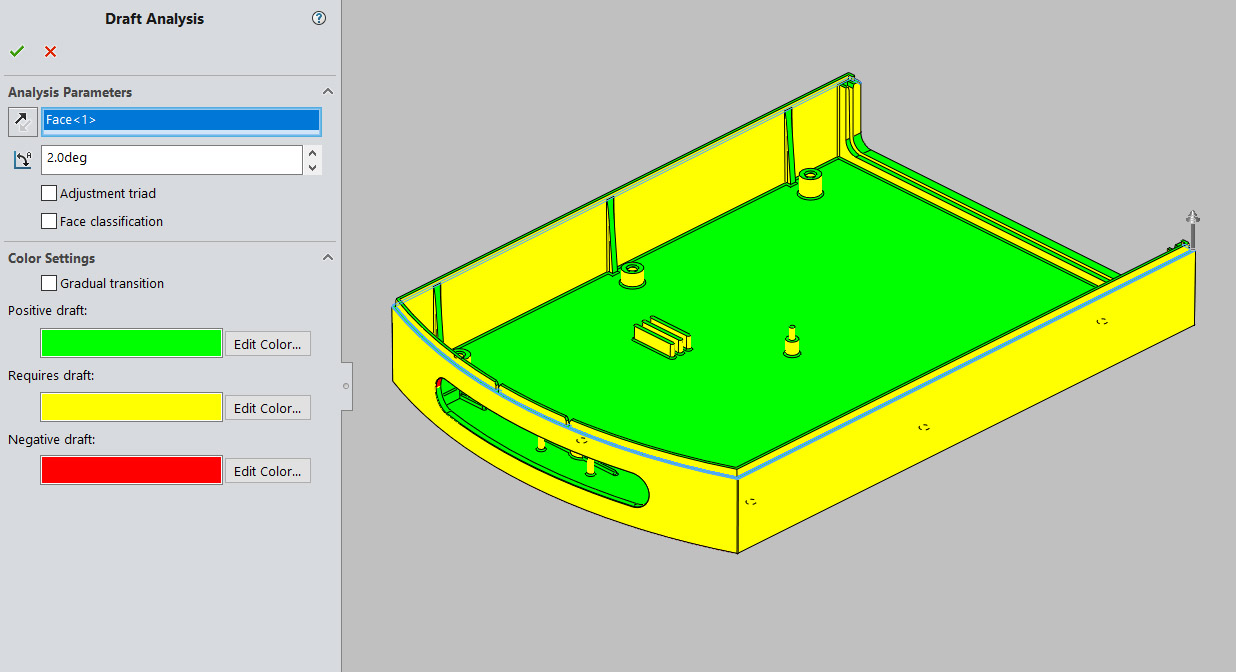
Fig. 8
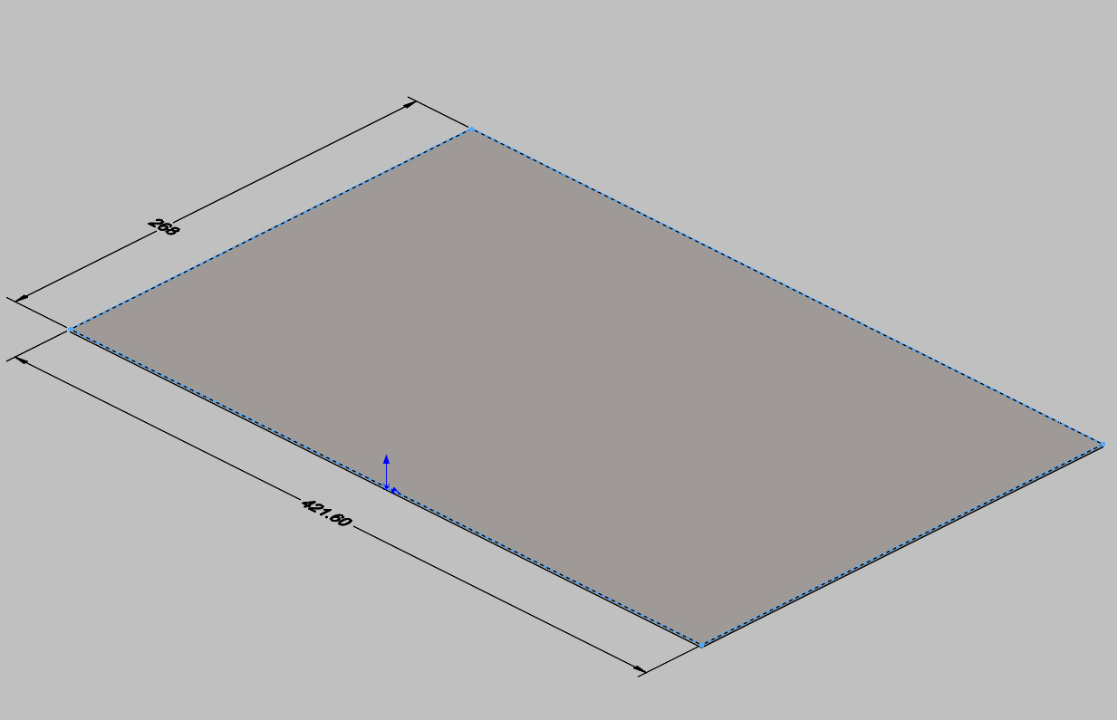
Fig. 9
A sheet metal part (e.g. folded Chassis Base) is created in a different way. Since the part thickness is uniform, the initial 2D sketch can be used to define the outline of the main face of the part. In the case of the SA30 Chassis this is the rectangular base. This is ‘thickened’ to create a flat plate or sheet (Fig.9).
Flanges of a specified height and angle (usually 90 degrees for us) can be added to selected edges e.g. to form the chassis sides (Fig.10). As with extruded parts, material can be removed using Cut operations to create holes and cut-outs as required.
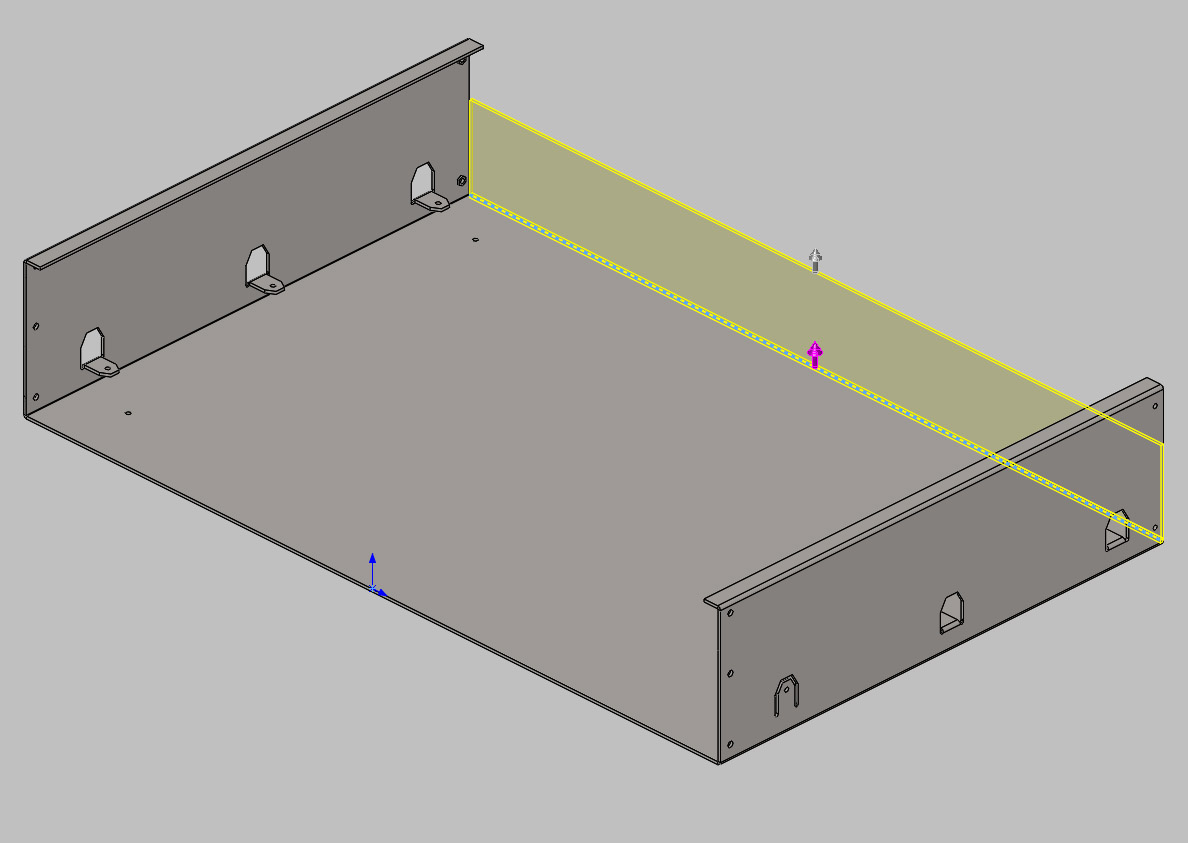
Fig. 10
The bend parameters (e.g. thickness and bend radius) are defined at the initial stage of sheet metal part creation. This allows the completed part to be unfolded (flattened) to define the outline of the cut sheet required to make it. This contrasts with extruded part creation, as it works backwards to the manufacturing process – first the folded shape is created, then flattened to obtain the shape of the cut sheet. As with draft angles on moulded parts, most suppliers’ CADCAM systems do the ‘flattening.’ They apply allowances specific to their machines and materials to allow for distortion during the folding process. Accurate values for bend allowance are only reliably obtained by physical testing.
We hope this article has provided some understanding of designing with 3D CAD. If you're interested in more information, please contact your local Design Engineer.